Solid oxide fuel cell stack

a fuel cell and solid oxide technology, applied in the direction of cell components, electrochemical generators, electrolytes, etc., can solve the problems of insufficient electrical conductivity of ceramic interconnectors, disadvantageous incorporation of ceramic interconnectors into porous electrodes, and small thickness, so as to achieve excellent power generation performance, suppress the formation of counter cells, and effectively suppress the effect of power generation performan

Active Publication Date: 2018-06-19
MORIMURA SOFC TECH CO LTD
View PDF8 Cites 0 Cited by
  • Summary
  • Abstract
  • Description
  • Claims
  • Application Information

AI Technical Summary

Benefits of technology

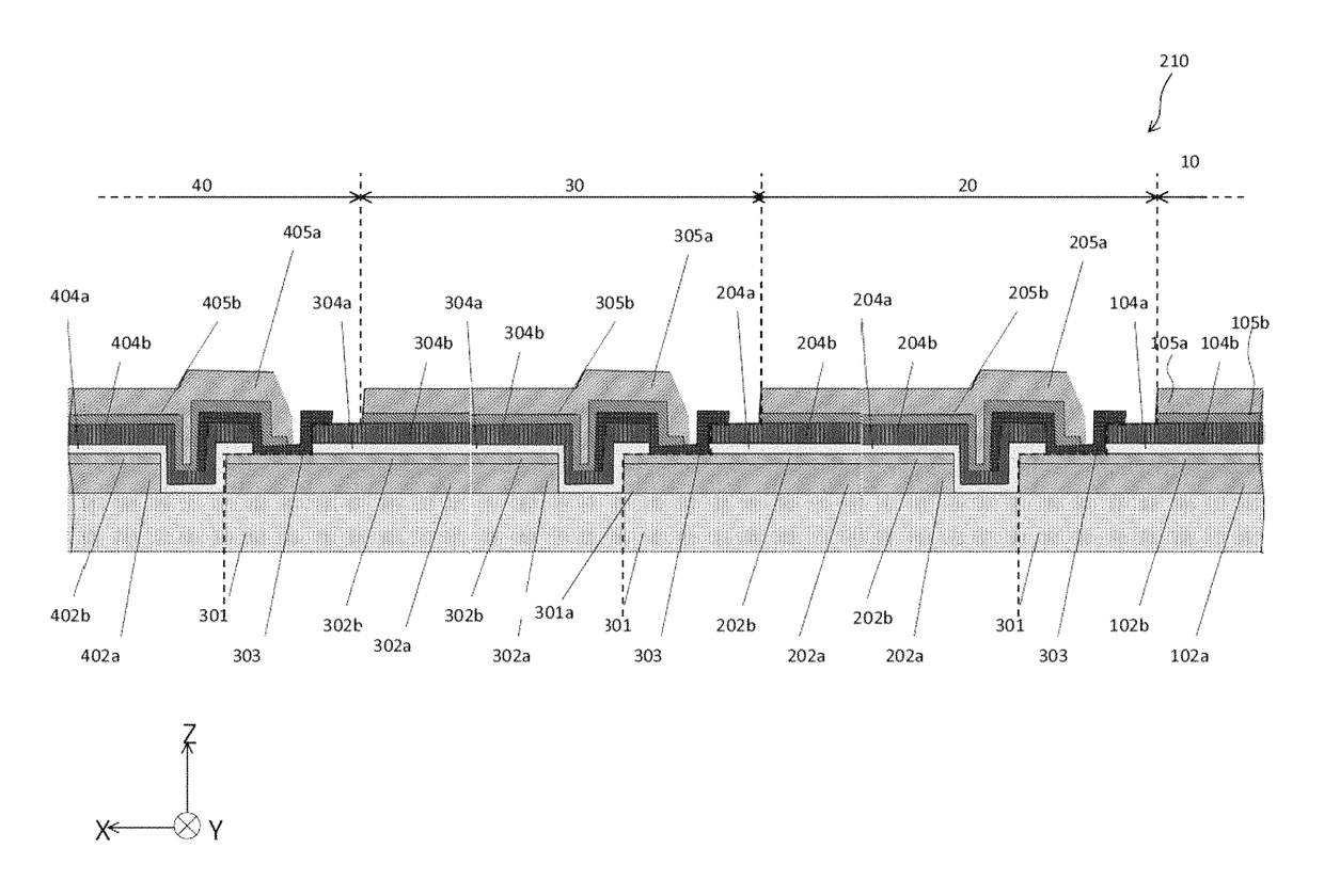
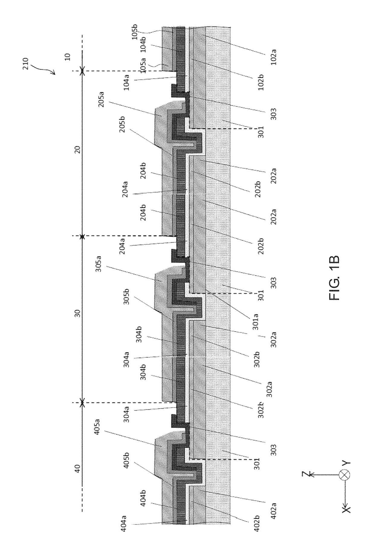
[0015]The present inventors have now found that the formation of a counter cell can be suppressed by providing, in a solid oxide fuel cell stack including a solid electrolyte provided between adjacent fuel electrodes, an insulating member on a solid electrolyte in adjacent one power generation element and between an air electrode in the adjacent one power generation element and the solid electrolyte therein. Further, the present inventors have found that a lowering in power generation performance can be effectively suppressed by covering the whole area of the surface of an interconnector with the air electrode in the one power generation element and that, as a result, a solid oxide fuel cell stack that has an excellent power generation performance, that is, a high power generation output, can be manufactured. The present invention has been made based on such findings.
[0016]Thus, an object of the present invention is to provide a solid oxide fuel cell stack that can suppress the formation of a counter cell, has a high electrical conductivity, and has a excellent power generation performance.

Problems solved by technology

In general, a ceramic interconnector cannot provide satisfactory electrical conductivity unless the thickness is small, for example, approximately not more than 100 μm.
When an attempt is made to form a ceramic interconnector having a reduced small thickness so as to obtain satisfactory electrical conductivity on a surface of porous electrodes such as fuel electrodes and air electrodes, there is a possibility that the ceramic interconnector is disadvantageously incorporated into the porous electrode.
This leads to a disadvantage of a possibility that the ceramic interconnector cannot be formed or a possibility that, even when the ceramic interconnector can be formed, the thickness is so small that satisfactory gas sealing properties cannot be obtained.
When the gas sealing property of the ceramic interconnector is low, the fuel gas is disadvantageously leaked from the fuel electrode side of the ceramic interconnector to the air electrode side, resulting in mixing with air.
When the electrical conductivity of a ceramic interconnector is low, the resistance of the ceramic interconnector is so high that the output of the fuel cell is disadvantageously lowered.
Further, when the oxide ion insulating property of a ceramic interconnector is low, the oxide ions are disadvantageously leaked from the air electrode side to the fuel electrode side of the interconnector, leading to a lowered efficiency of the fuel cell.
In addition, when the adhesion between the solid electrolyte and the ceramic interconnector is low, disadvantageously, gaps such as cracking occur between the solid electrolyte and the ceramic interconnector, resulting in leakage of the fuel gas through the gaps.
Further, since chromium (Cr) is contained, there is a possibility that the so-called Cr poisoning occurs.
This causes the formation of a counter cell that generates electromotive force in a direction opposite to electromotive force originally generated in the power generation element, leading to lowered power generation performance.
In the solid oxide fuel cell described in PTL 2, however, since a part of the interconnector is covered with the solid electrolyte, a lowering in power generation performance cannot be effectively suppressed without difficulties.

Method used


Image

  • Solid oxide fuel cell stack
  • Solid oxide fuel cell stack
  • Solid oxide fuel cell stack

Examples


examples

[0157]The present invention is further illustrated by the following Examples and Comparative Examples that are not intended as a limitation of the scope of the present invention.

example a1

Preparation of Green Body A for Support

[0158]A Raw Material Powder of a High-Purity Forsterite (Mg2SiO4 containing 0.05% by mass of CaO) was regulated to a mean particle diameter of 0.7 μm. 100 parts by weight of this powder, 20 parts by weight of a solvent (water), 8 parts by weight of a binder (methylcellulose), 0.5 part by weight of a lubricant, and 15 parts by weight of a pore forming agent (acrylic resin particles having a mean particle diameter of 5 μm) were mixed in a rapid mixer, the mixture was kneaded in a kneader, the kneaded product was deaerated with a vacuum pug mill to prepare a green body for extrusion molding The mean particle diameter was measured according to JIS R1629 and expressed in terms of 50% diameter (the same shall apply hereinafter).

[0159]Preparation of Slurry for Fuel Electrode Layer

[0160]A NiO powder and a 10YSZ (10 mol % Y2O3-90 mol % ZrO2) power were mixed together by wet mixing at a weight ratio of 65:35 to obtain a dry powder. The dry powder thus ob...

example a2

[0182]A solid oxide fuel cell stack was obtained in the same manner as in Example A1, except that L′ / L was 50. The solid oxide fuel cell stack thus obtained was evaluated as follows. The results are shown in Table 1.


PUM

PropertyMeasurementUnit
thicknessaaaaaaaaaa
thicknessaaaaaaaaaa
thicknessaaaaaaaaaa

Abstract

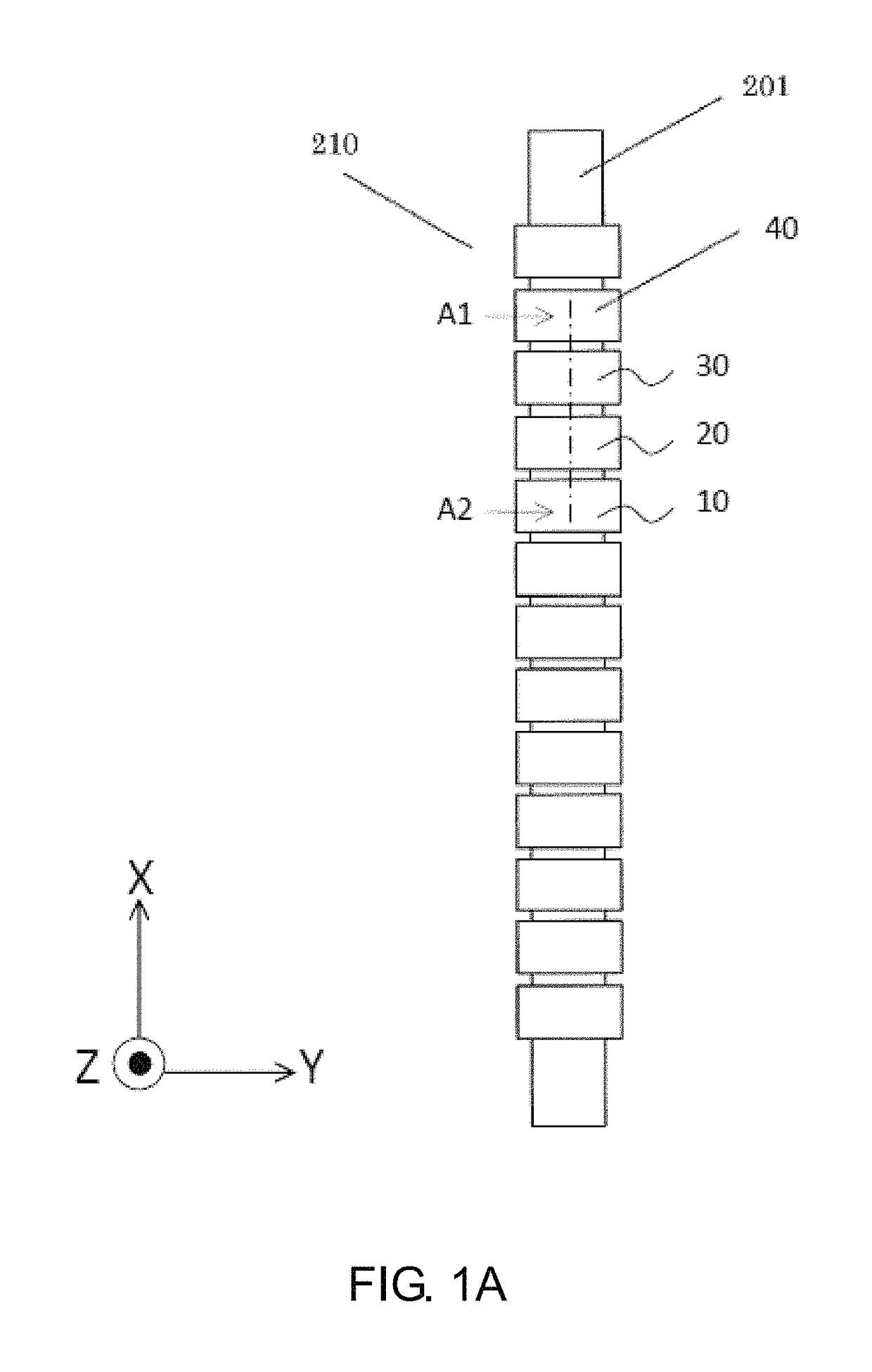
A solid oxide fuel cell stack includes a support, a plurality of power generation elements provided on a surface of the support, the plurality of power generation elements connected in series, each including at least a fuel electrode, a solid electrolyte, and an air electrode stacked in that order, and an interconnector that electrically connects an air electrode in one of adjacent power generation elements to a fuel electrode in the other power generation element. A solid electrolyte in adjacent one power generation element is provided between a fuel electrode in the adjacent one power generation element and the fuel electrode in the adjacent other power generation element, and an insulating member is provided at a position that is on the solid electrolyte in the adjacent one power generation element and between the air electrode in the adjacent one power generation element and the solid electrolyte therein.

Description

FIELD OF INVENTION[0001]The present invention relates to a solid oxide fuel cell stack. More specifically, the present invention relates to a solid oxide fuel cell stack that can suppress the formation of a counter cell, has a high electrical conductivity, and has a excellent power generation performance.BACKGROUND ART[0002]Fuel cells are energy converters that, unlike heat engines which go through heat energy and kinetic energy processes, include reacting fuels such as natural gas and hydrogen with oxygen in the air through a solid electrolyte and continuously and directly obtaining electric energy from chemical energy possessed by fuels. Among them, solid oxide fuel cells are fuel cells that operate as cells including a solid oxide (ceramic) as a solid electrolyte, a fuel electrode as a negative electrode, and an air electrode as a positive electrode. Further, solid oxide fuel cells are known as having an advantage that a high energy conversion efficiency can be obtained.[0003]In ...

Claims


Application Information

Patent Timeline
Patent Type & Authority Patents(United States)
IPC IPC(8): H01M8/02H01M8/0217H01M4/90H01M8/2465H01M8/243H01M8/00H01M8/0202H01M8/1246H01M8/24H01M8/12H01M8/10H01M8/124
CPCH01M8/243H01M8/2465H01M8/1246H01M8/0202H01M4/9033H01M8/0217H01M8/24H01M2300/0071H01M2008/1293H01M8/02H01M8/10Y02E60/50
Inventor KAKINUMA, YASUOOKAMOTO, OSAMUANDO, SHIGERUMURAKAMI, HIRONOBUFURUYA, SEIKIMOMIYAMA, YUTAKAHAYAMA, KIYOSHIWATANABE, NAOKITANAKA, SHUHEIISAKA, NOBUOHOSHIKO, TAKUYASATO, MASAKI
Owner MORIMURA SOFC TECH CO LTD
Why Eureka
Try Eureka