Image capturing apparatus and control method of image sensor

a technology of image sensor and capture apparatus, which is applied in the field of image capture apparatus and control method of, can solve the problems of increasing system load, increasing output rate, and increasing the number of output channels, and achieve the effect of reducing system load and energy consumption and not degrading the accuracy of focus detection

Active Publication Date: 2018-06-19
CANON KK
View PDF4 Cites 0 Cited by
  • Summary
  • Abstract
  • Description
  • Claims
  • Application Information

AI Technical Summary

Benefits of technology

[0009]The present invention has been made in consideration of the above situation, and to reduce a system load and energy consumption without degrading accuracy of focus detection.

Problems solved by technology

On the other hand, as the number of pixels in an image sensor increases, it is necessary to readout larger number of pixels than ever within a predetermined period of time, which causes an increase in system load due to an increase in output rate of the image sensor or an increase in the number of output channels.
For example, there is a problem in which, if the number of output channels increases, or if the output rate increases with the number of channels being unchanged, adjustment of signal delay amount between the channels becomes more complicated.
Further, a problem arises such that energy consumption increases by reading a larger number of signals.
However, in Japanese Patent Laid-Open No. 2012-155095, since a signal is independently read out from each of the photoelectric conversion portions, the period of time required for reading out signals cannot be sufficiently shortened.
In this case, there is a problem in which, when a subject is moving, it is difficult to perform focus control while sufficiently tracking the moving subject.
The accuracy of performing focus detection while tracing a moving subject improves as the number of regions from which signals are read out without being added increases, but the problems regarding the increase in system load and the increase in power consumption cannot be solved.
Therefore, a problem that from which area in a frame a focus control signal of phase difference method is to be read out is posed.

Method used


Image

  • Image capturing apparatus and control method of image sensor
  • Image capturing apparatus and control method of image sensor
  • Image capturing apparatus and control method of image sensor

Examples


first embodiment

Configuration of Image Capturing System

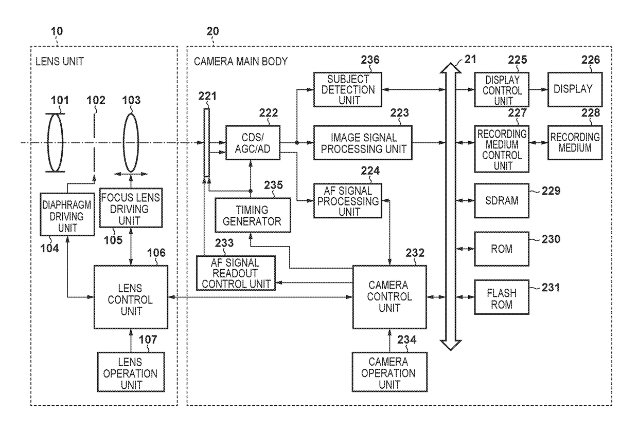
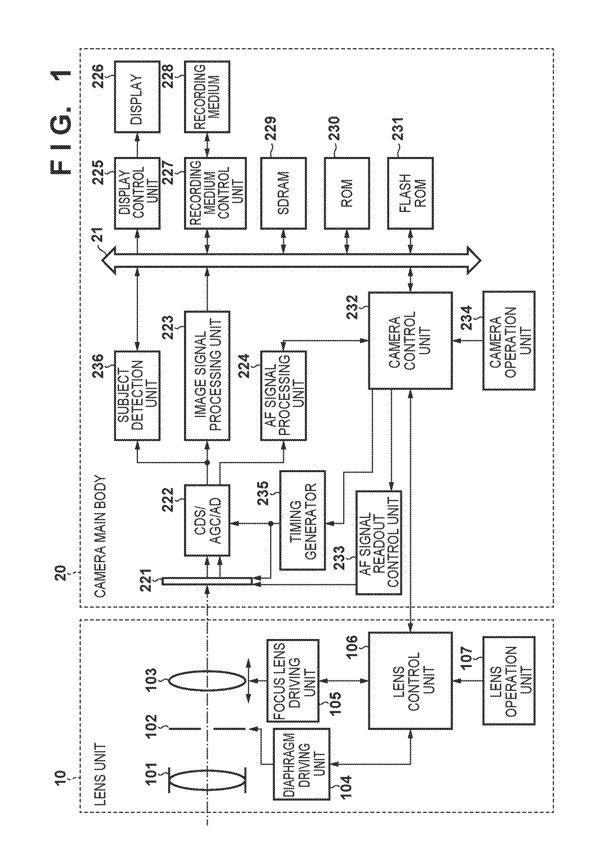
[0028]FIG. 1 is a block diagram showing a schematic configuration of an image capturing system according to a first embodiment of the present invention. In the first embodiment, a lens-exchangeable image capturing system is explained as an example, however, the present invention can be applied to an image capturing system with a fixed lens unit.

[0029]As shown in FIG. 1, the image capturing system of the first embodiment is formed from a lens unit 10 and a camera main body 20. A lens control unit 106 for controlling overall operation of the lens unit 10 and a camera control unit 232 for controlling overall operation of the image capturing system including the lens unit 10 communicates data with each other via a terminal provided on a lens mount.

[0030]First, a structure of the lens unit 10 will be explained. The lens unit 10 includes an imaging optical system formed from a fixed lens 101, a diaphragm 102, a focus lens 103, and so forth. The diaph...

second embodiment

[0062]Next, a description will be given of a second embodiment of the present invention. In the first embodiment as described above, it is explained that, in a case where the subject in a shot image is moving in the horizontal direction, the divided readout is performed every predetermined number of rows. By contrast, in the second embodiment, in a case where an image capturing system moves in the horizontal direction, it is controlled such that the divided readout is performed every predetermined number of rows.

[0063]FIG. 7 is a block diagram of a schematic configuration of an image capturing system according to the second embodiment. FIG. 7 differs from FIG. 1 in the point that a camera main body 20′ further has a camera movement detection unit 701. Other constituents are the same as those described in the first embodiment, the same reference numerals are used, and an explanation of them are omitted.

[0064]The camera movement detection unit 701 is formed from, for example, a known ...

third embodiment

[0071]Next, a description will be given of a third embodiment of the present invention. The image sensor used in the first embodiment can be selectively read out by the divided readout or the added readout in units of rows, by contrast, in the third embodiment, the image sensor can be controlled to be read out by the divided readout or the added readout also in units of columns.

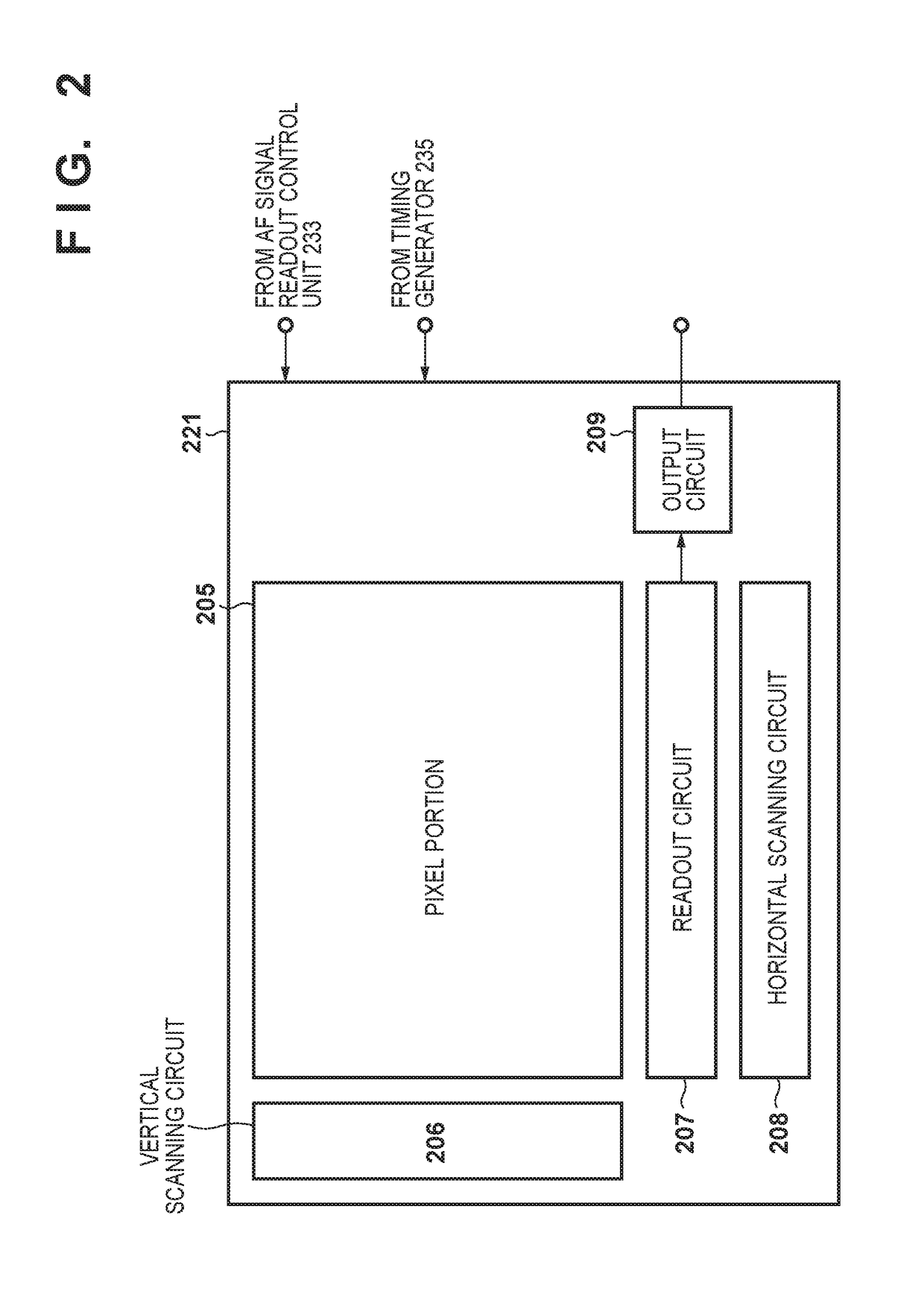
[0072]FIG. 9 shows a configuration of an image sensor 221′ according to the third embodiment. The image sensor 221′ shown in FIG. 9 differs from the image sensor 221 shown in FIG. 2 in that the image sensor 221′ has two horizontal scanning circuits, namely, the first horizontal scanning circuit 208a and the second horizontal scanning circuit 208b. The first horizontal scanning circuit 208a controls the readout circuit 207 such that a signal read out to the readout circuit 207 is sequentially transferred to the output circuit 209. The second horizontal scanning circuit 208b controls the readout circuit 207 suc...


PUM


Abstract

An image capturing apparatus comprising: an image sensor that has a plurality of photoelectric conversion portions corresponding to each of a plurality of microlenses arranged in two-dimensions, and outputs an image signal corresponding to a quantity of incident light; a detection unit configured to detect a moving direction of a subject; a determination unit configured to, in a case where the subject is moving in a main scanning direction, determine to perform divided readout in every predetermined number of rows, and to perform added readout in the rows except for the every predetermined number of rows; and a control unit configured to control the image sensor by switching between the divided readout and the added readout in units of rows based on the determination result.

Description

BACKGROUND OF THE INVENTION[0001]Field of the Invention[0002]The present invention relates to an image capturing apparatus and a control method of an image sensor capable of reading out from each pixel a pair of signals corresponding to light beams that have passed through different pupil regions of an optical system.[0003]Description of the Related Art[0004]Conventionally, a technique for realizing focus detection function and an image signal acquisition using one image sensor has been known, and as an example, an image sensor capable of using pixels for acquiring information for focus detection as pixels for acquiring an image for display / record has been proposed (see Japanese Patent Laid-Open No. 2007-325139). According to this technique, among pixels that form an image sensor, each of at least part of the pixels is divided into a plurality of regions in the horizontal and / or vertical direction, and upon acquiring an image, an image signal is obtained by adding signals obtained f...

Claims


Application Information

Patent Timeline
Patent Type & Authority Patents(United States)
IPC IPC(8): H04N5/232H04N5/3745H04N5/369H04N5/14
CPCH04N5/23212H04N5/144H04N5/3696H04N5/37457H04N23/672H04N25/704H04N25/778
Inventor KAIBARA, HIROSHI
Owner CANON KK
Why Eureka
Try Eureka