Apparatus and method for attenuation of vibration in machine tool

a machine tool and vibration attenuation technology, applied in the field of apparatus and method for attenuating vibration in the machine tool, can solve the problems of reducing not only the durability of the machine and a structure, but also the loss of machine tools, and achieves excellent cost saving effect, increase the lifetime of the machine tool, and improve the precision of processing with the machine tool

Active Publication Date: 2018-07-03
KOREA INST OF MACHINERY & MATERIALS
View PDF31 Cites 0 Cited by
  • Summary
  • Abstract
  • Description
  • Claims
  • Application Information

AI Technical Summary

Benefits of technology

[0012]The present invention has been made in an effort to provide an apparatus and method for attenuation of vibration in a machine tool having an advantage of making dissipative interference of a vibration wave form.
[0028]The apparatus and method for attenuation of vibration in a machine tool according to an exemplary embodiment of the present invention can improve precision of processing with a machine tool, and can increase a lifetime of the machine tool to accordingly provide an excellent cost saving effect, by measuring vibration in real time and attenuating the vibration based on a result of the measurement.

Problems solved by technology

The machine tool inevitably undergoes vibration due to design errors and disturbances.
The vibration is a major cause of reduction of not only durability of the machine and a structure, but also precision reduction of a processed article to cause very large losses.
Since levels and frequencies of vibrations, such as a vibration occurring at a structure / machine itself and a vibration applied thereto by disturbance, always vary, the above methods have a limitation not only on a wide frequency band design, but also in applicability due to very high replacement cost, and working cost for a change such as design modification.
Since it is impossible to utilize the passive methods for a variety of processes and processing conditions, structural design changes result, which causes additional time and cost (e.g., a design change and replacement work cost), and accordingly the passive methods are not effective.

Method used


Image

  • Apparatus and method for attenuation of vibration in machine tool
  • Apparatus and method for attenuation of vibration in machine tool
  • Apparatus and method for attenuation of vibration in machine tool

Examples


Embodiment Construction

[0037]Hereafter, an apparatus and method for attenuation of vibration in a machine tool in accordance with an exemplary embodiment of the present invention will be described with reference to accompanying drawings.

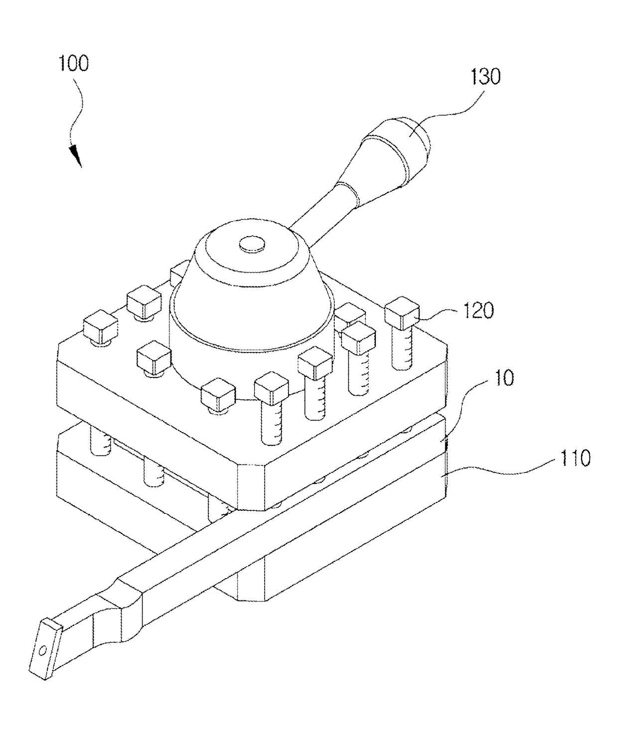
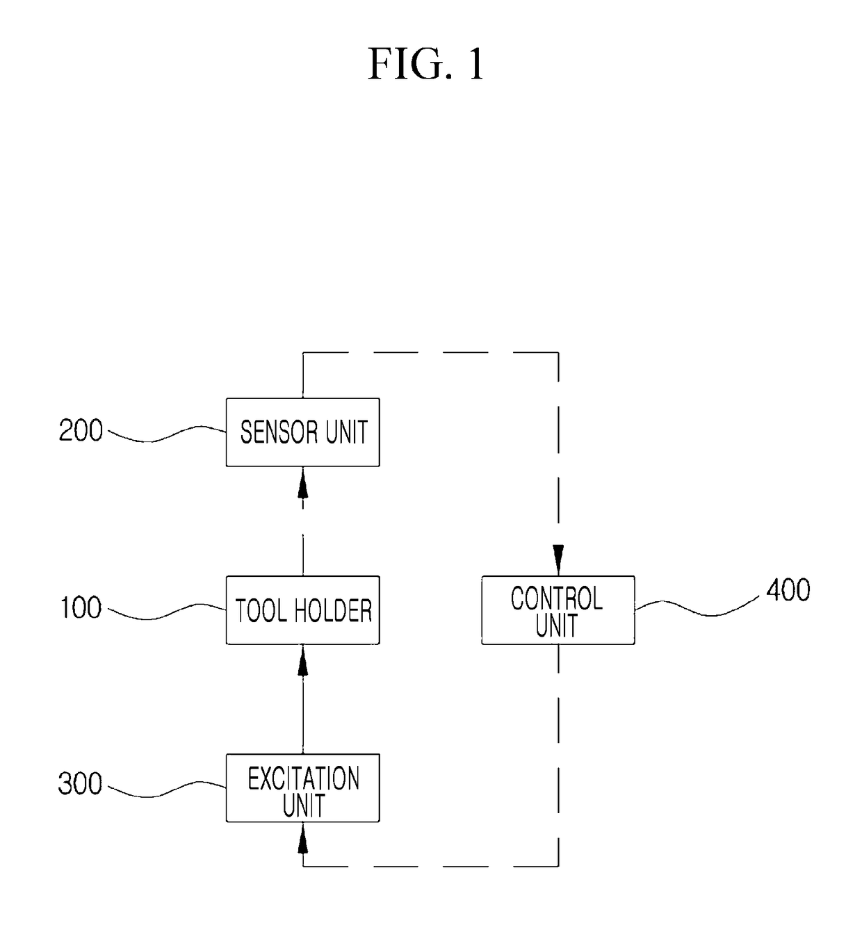
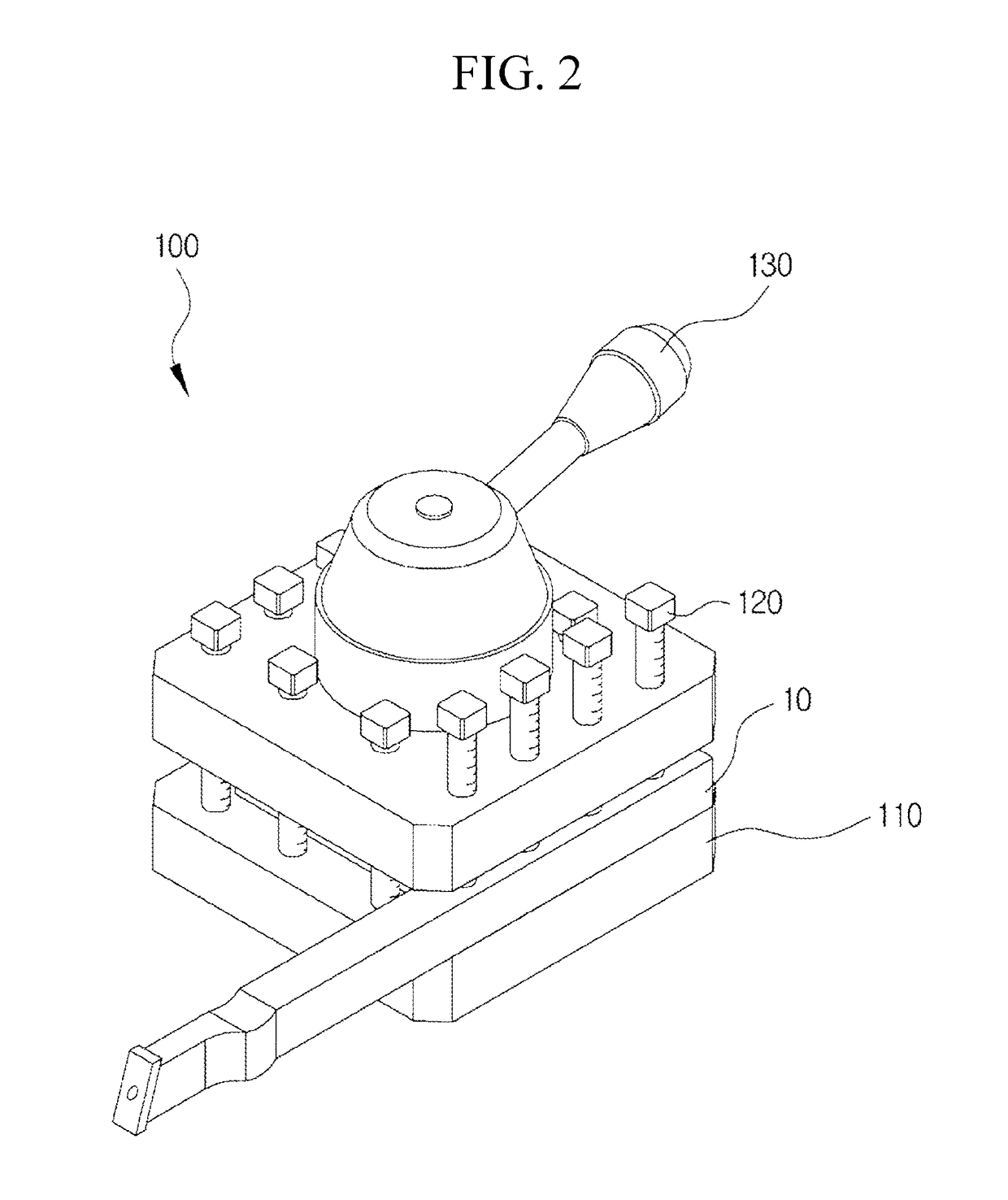
[0038]FIG. 1 illustrates a block diagram of an apparatus for attenuation of vibration in a machine tool in accordance with an exemplary embodiment of the present invention, FIG. 2 illustrates a perspective view of an apparatus for attenuation of vibration in a machine tool in accordance with an exemplary embodiment of the present invention, FIG. 3 illustrates a perspective view of a tool holder in an apparatus for attenuation of vibration in a machine tool in accordance with an exemplary embodiment of the present invention, FIG. 4 illustrates an exploded perspective view of a tool holder in an apparatus for attenuation of vibration in a machine tool in accordance with an exemplary embodiment of the present invention, FIG. 5 illustrates a perspective view of an excitation u...


PUM


Abstract

The present invention relates to an apparatus and method for attenuation of vibration in a machine tool, and more particularly, to an apparatus and method for attenuation of vibration in a machine tool in which a vibration of a machine tool is measured, and generates an identical frequency with a piezoelectric actuator as well as changes a phase for making dissipative interference of a generated vibration wave form.

Description

CROSS-REFERENCE TO RELATED APPLICATION[0001]This application is a National Stage application of PCT / KR2013 / 008236 filed on Sep. 11, 2013, which claims priority to Korean Patent Application No. 10-2012-0109784, filed on Oct. 4, 2012.BACKGROUND OF THE INVENTION[0002](a) Field of the Invention[0003]The present invention relates to an apparatus and method for attenuation of vibration in a machine tool, and more particularly, to an apparatus and method for attenuation of vibration in a machine tool in which a vibration of a machine tool is measured and an identical frequency is generated with a piezoelectric actuator, and changes a phase for making dissipative interference of the generated vibration wave form.[0004](b) Description of the Related Art[0005]A machine tool is generally regarded as a machine for mechanical fabrication. The machine tool is a machine for processing metal and other materials by cutting off, cutting, boring, drilling, screw cutting, grinding, and so on with a cut...

Claims


Application Information

Patent Timeline
Patent Type & Authority Patents(United States)
IPC IPC(8): G05B21/00G05B19/404B23B29/12B23Q11/00B23B29/24G05B15/02
CPCB23B29/125B23B29/244B23Q11/0032G05B15/02G05B19/404Y10T82/2585B23B2250/16B23B2260/108G05B2219/37434G05B2219/49176B23B27/00B23B29/00B23Q11/00
Inventor KIM, DONG-HOONSONG, JOON YUB
Owner KOREA INST OF MACHINERY & MATERIALS
Why Eureka
Try Eureka