Unlock instant, AI-driven research and patent intelligence for your innovation.

Method of control for synchronous rectifiers

a technology of synchronous rectifiers and control methods, applied in the direction of energy industry, efficient power electronics conversion, electric variable regulation, etc., can solve the problems of body diode conduction, negative current flow, loss increase, etc., and achieve the effect of minimising the measurement value over tim

Active Publication Date: 2018-07-03
EISERGY
View PDF7 Cites 0 Cited by
  • Summary
  • Abstract
  • Description
  • Claims
  • Application Information

AI Technical Summary

Benefits of technology

[0014]This control function suitably seeks to minimise the measurement value over time.

Problems solved by technology

However a known difficulty with using actively controlled switches such as MOSFETs is that the timing for controlling the switch is important to ensure efficient operation.
Turning off a switch too early may result in body diode conduction and turning off the switch too late may result in negative current flow.
In both of these cases, losses increase.
Disadvantages associated with these approaches include sensing difficulties in terms of timing and in terms of power loss.

Method used


Image

  • Method of control for synchronous rectifiers
  • Method of control for synchronous rectifiers
  • Method of control for synchronous rectifiers

Examples


Embodiment Construction

[0025]The application will now be described with reference to an exemplary switching converter, and more particularly an LLC resonant converter. The LLC converter is used in switching converters which include a power factor correction deployment, typically between a capacitor fed from a power-factor correction stage and the load.

[0026]The operation of the circuit is well known and would be familiar to those skilled in the art.

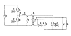
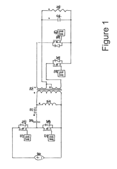
[0027]In brief, as shown in FIG. 1, two primary side switches 24 and 26 are operated as a symmetric half-bridge with a nominally 50:50 drive ratio. A small dead-time is generally introduced to allow current to drive the drain voltage of the switch that is about to conduct to zero.

[0028]The output from the symmetric half bridge is connected to a capacitor 28 which in turn is connected to and drives an inductor / transformer assembly 31, 30 and 32. The inductor / transformer assembly comprises an inductor 31 which is in series with the capacitor and the parallel comb...


PUM


Abstract

The present application relates to the field of switching power supplies and in particular to switching power supplies in which a primary side is isolated from the secondary side and in which a synchronous rectifier on the secondary side is controlled from the primary side. The application provides a method for minimizing body diode conduction losses.

Description

FIELD OF THE APPLICATION[0001]The present application relates to the field of switching power supplies and in particular to switching power supplies employing a synchronous rectifierBACKGROUND OF THE APPLICATION[0002]In isolated switching supplies the general principle is that a primary side voltage is switched through a winding on the primary side of a transformer. One or more rectifiers are employed at the secondary side of the transformer in the provision of an output voltage.[0003]Whilst a variety of different topologies are known including Flyback, LLC and Forward converters, the general principle remains.[0004]There is always a general desire to improve the efficiency of switching supplies. The use of a conventional p-n junction diode as a rectifier causes a power loss in the diode arising from a voltage drop across the diode of anywhere between 0.7 V and 1.7 V. This can be improved upon using Schottky diodes which exhibit lower voltage drops (as low as 0.3 volts).[0005]Howeve...

Claims


Application Information

Patent Timeline
Patent Type & Authority Patents(United States)
IPC IPC(8): H02M3/335H02M1/00
CPCH02M3/33592H02M2001/0058Y02B70/1491Y02B70/1475Y02B70/1433H02M1/0058Y02B70/10Y02P80/10H02M3/1588H02M7/217
Inventor YOUNG, GEORGE
Owner EISERGY