Motor stator device with simple coil-winding structure

a stator device and motor technology, applied in the direction of dynamo-electric machines, electrical apparatus, magnetic circuit shapes/forms/construction, etc., can solve the problems of inability to perform the inner winding manner of the small low productivity, and inability to adapt the inner winding manner for the large-scale inner winding motor, so as to improve the convenience and efficiency of winding operation, reduce the cogging torque, and improve the noise and energy waste

Active Publication Date: 2018-07-10
ABLE ENTERPRISE
View PDF6 Cites 0 Cited by
  • Summary
  • Abstract
  • Description
  • Claims
  • Application Information

AI Technical Summary

Benefits of technology

[0007]Accordingly, an object of the present invention is to provide a motor stator device capable of decreasing the cogging torque to improve the noise and energy waste, and capable of improving the convenience and efficiency of the winding operation and thus promoting economic performance and market competitiveness.
[0008]Another object of the present invention is to provide a motor stator device having preferable stability in combination of the silicon steel sheets, so as to strengthen the structure of the stator.
[0009]To achieve the above-mentioned objects, the motor stator device encompassing a motor rotor includes an insulating base, a plurality of stator segments and a plurality of segment connectors, wherein the insulating base comprising an outer ring base, an inner ring base and a connection base. The connection base is secured between the outer ring base and the inner ring base. The outer ring base and the inner ring base are arc and respectively form a plurality of outer ring openings and a plurality of inner ring openings, the outer ring openings and the inner ring openings are communicated with each other to define holding spaces inside the connection base. The outer ring base and the inner ring base respectively form a plurality of outer ring sinks and a plurality of inner ring pillars. The outer ring sinks are alternatively arranged with the outer ring openings on the outer ring base while the inner ring pillars are arranged with the inner ring openings on the inner ring base. The connection base is provided to be wound with a metal coil. The stator segments are positioned on the insulating base. Each of the stator segments is shaped by stacking a plurality of silicon steel sheets with same structure. Each of the stator segments is arc and comprises an outer ring portion, an inner ring portion and a connection portion. The connection portion is secured between the outer ring portion and the inner ring portion. The connection portion is disposed in the holding space while the outer ring portion and the inner ring portion are respectively butted on outer edges of the outer ring opening and the inner ring opening. The segment connectors are positioned on the outer ring sinks between the insulating base and the stator segments. Each of the segment connectors is shaped by stacking a plurality of silicon steel sheets with same structure. Each of the segment connectors is arc and has a base part and an extension part opposite to the base part. The extension part is integrally extended from the base part and toward the motor rotor to get close to the inner ring pillar next to the motor rotor. Each of the silicon steel sheets of the stator segments has two separate convex ridges thereon which are both rectangular in shape and mutually perpendicular in orientation so as to bring preferable stability in combination of the silicon steel sheets in injection molding. Each of the silicon steel sheets of the segment connectors has a convex ridge which is rectangular in shape so as to bring preferable stability in combination of the silicon steel sheets.
[0010]In according with the present invention, interfaces among the outer ring base, the connection base and the inner ring base are defined as arc curved faces so as to expand winding space for facilitating winding operation.

Problems solved by technology

However, this inner winding manner can only be adapted for large-scale inner winding motors.
It is quite impossible to perform the inner winding manner for the small-scale inner winding motor by the coil-winding machine.
Yet, it seems time-consuming when performing it by hand, thus resulting in low productivity.
Furthermore, there are often problems with unsmooth rotation of rotor resulted from the effect of cogging torque during operations.
The cogging torque arises from the magnetic lines of force formed between the stator and the rotor, leading to the variation of torques and the jerky run of the rotor in particular at low speed, therefore causing noise and energy waste.
However, the convex ridge is usually designed as circular shape, which brings in instability in combination of the silicon steel sheets, and leads to structural weakness of the stator.

Method used


Image

  • Motor stator device with simple coil-winding structure
  • Motor stator device with simple coil-winding structure
  • Motor stator device with simple coil-winding structure

Examples


Embodiment Construction

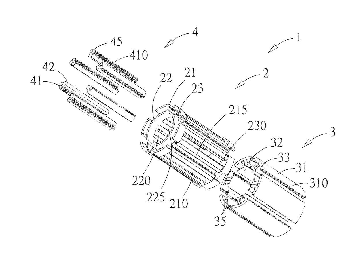
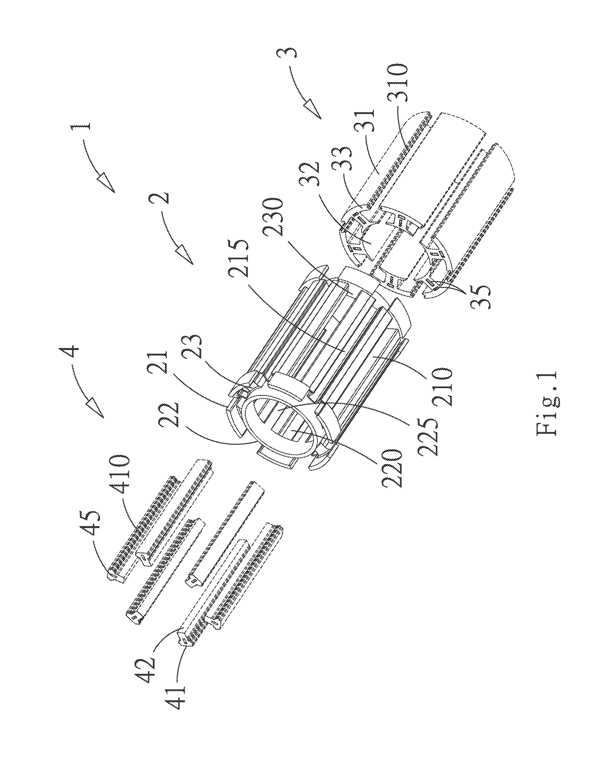
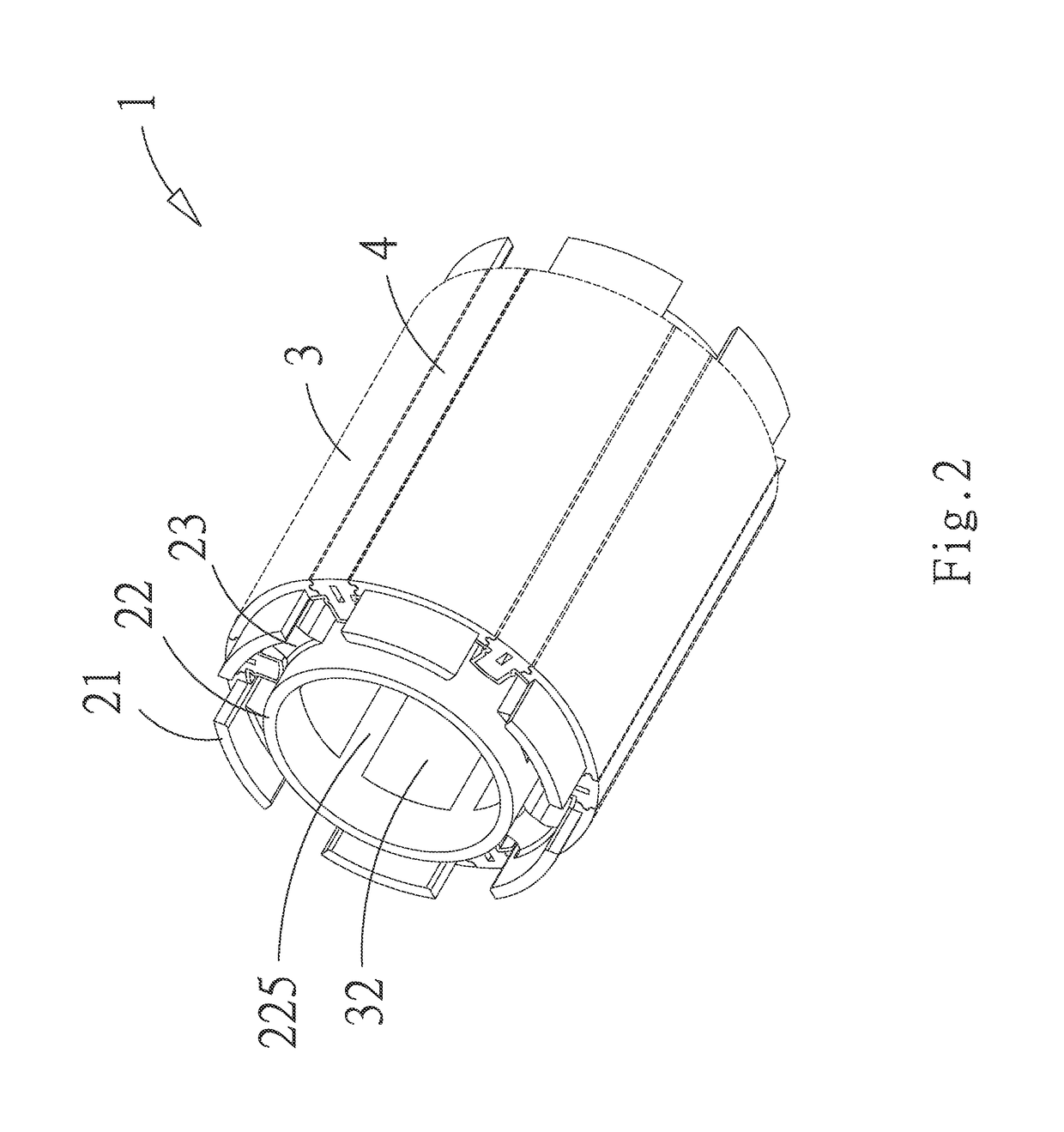
[0015]Referring to FIG. 1 to FIG. 4, a motor stator device 1 of the present invention includes an insulating base 2, a plurality of stator segments 3 and a plurality of segment connectors 4. The insulating base 2 has a cylinder shape and encompasses a motor rotor (not shown). The insulating base 2 comprises an outer ring base 21, an inner ring base 22 and a connection base 23. The connection base 23 is secured between the outer ring base 21 and the inner ring base 22. The outer ring base 21 and the inner ring base 22 are arc and respectively form a plurality of outer ring openings 210 and a plurality of inner ring openings 220. The outer ring openings 210 and the inner ring openings 220 are communicated with each other to define holding spaces 230 inside the connection base 23. Further, the outer ring base 21 and the inner ring base 22 respectively form a plurality of outer ring sinks 215 and a plurality of inner ring pillars 225. The outer ring sinks 215 are alternatively arranged ...


PUM


Abstract

A motor stator device with simple coil-winding structure is disclosed. The motor stator device includes an insulating base comprising an outer ring base, an inner ring base and a connection base, the outer ring base and the inner ring base alternatively forming outer ring openings, inner ring openings, outer ring sinks and inner ring pillars, the connection base being provided to be wound with a metal coil; a plurality of stator segments being positioned on the insulating base; and a plurality of segment connectors being positioned on the outer ring sinks between the insulating base and the stator segments and having a base part and an extension part opposite to the base part, the extension part being integrally extended from the base part and toward the motor rotor to get close to the inner ring pillar next to the motor rotor, so as to decrease the cogging torque.

Description

BACKGROUND OF THE INVENTION[0001]1. Field of the Invention[0002]The present invention relates to a motor stator device, and more particularly to a motor stator device with simple coil-winding structure capable of decreasing the cogging torque to improve the noise and energy waste, and capable of improving the convenience and efficiency of the winding operation and thus promoting economic performance and market competitiveness.[0003]2. Related Art[0004]Conventionally, a motor has a stator and a rotor, wherein the stator includes an outer ring portion, a connection portion and an inner ring portion. The outer ring portion is a closed circular body. The inner ring portion has openings that are disposed at intervals. The connection portion is connected between the outer ring portion and the inner ring portion. The inner ring portion is used for receiving the rotor. The connection portion is wound with a metal coil in a lengthwise direction. When current is conducted to the metal coil, t...

Claims


Application Information

Patent Timeline
Patent Type & Authority Patents(United States)
IPC IPC(8): H02K3/28H02K1/14H02K29/03
CPCH02K1/148H02K3/28H02K29/03
Inventor CHUANG, YEN-PENG
Owner ABLE ENTERPRISE
Why Eureka
Try Eureka