Axial gap electronic motor

a technology of electronic motors and axial gaps, applied in the direction of rotating magnets, magnetic circuit rotating parts, synchronous machines with stationary armatures, etc., can solve the problems of skews having drawbacks, reducing the efficiency of conversion to rotational energy, vibration and noise, etc., to reduce vibration caused by cogging torque, reduce cost, and prevent the effect of increasing cogging torqu

Active Publication Date: 2006-11-14
FUJITSU GENERAL LTD
View PDF12 Cites 22 Cited by
  • Summary
  • Abstract
  • Description
  • Claims
  • Application Information

AI Technical Summary

Benefits of technology

[0007]The present invention has been made to solve the above-described problems, and accordingly an object of the present invention is to provide an axial gap electronic motor capable of decreasing cogging torque and thus decreasing vibrations and noise.
[0008]To achieve the above object, the present invention has some features described below. First, the invention of a first aspect is characterized in that in an axial gap electronic motor in which a stator and a rotor are arranged opposedly along the rotation axis direction of the rotor with a predetermined gap being provided therebetween, the stator has a magnetic force generating section in which a plurality of stator iron cores consisting of magnetic bodies are arranged in a ring shape on a concentric circle with the rotation axis line of the rotor being the center axis, each of teeth of the stator iron core is provided with a skew. According to this invention, the teeth of stator iron core are provided with a skew, by which the occurrence of cogging torque is reduced, so that the vibrations and noise of rotor can be decreased.

Problems solved by technology

If this cogging torque is high, vibrations and noise occur.
Therefore, there is a fear that the rotor is brought into contact with the stator by vibrations, which may provide a cause of breakage, etc.
On the other hand, however, the skew has a drawback of decreased efficiency of conversion to rotational energy.

Method used


Image

  • Axial gap electronic motor
  • Axial gap electronic motor
  • Axial gap electronic motor

Examples


Embodiment Construction

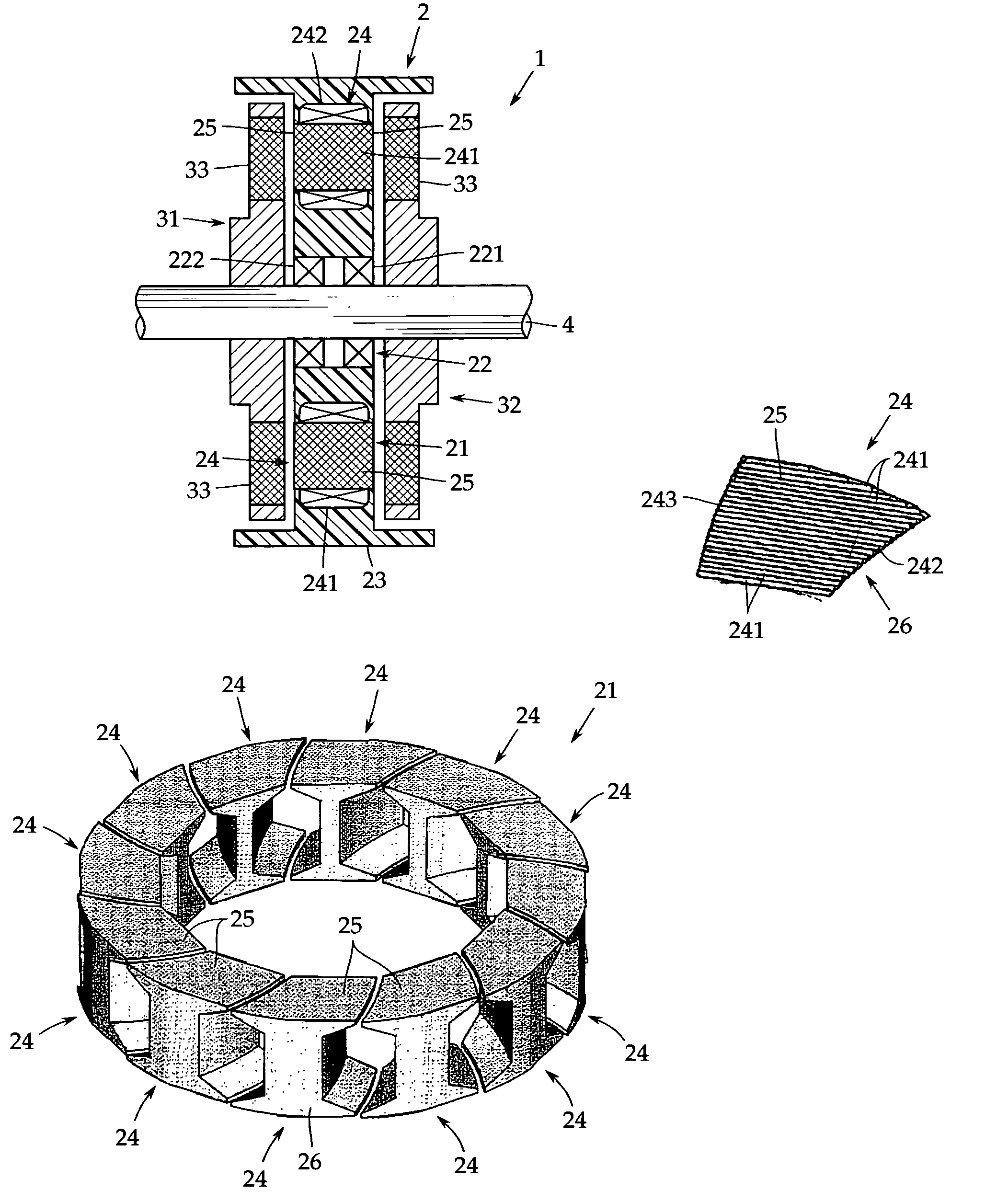
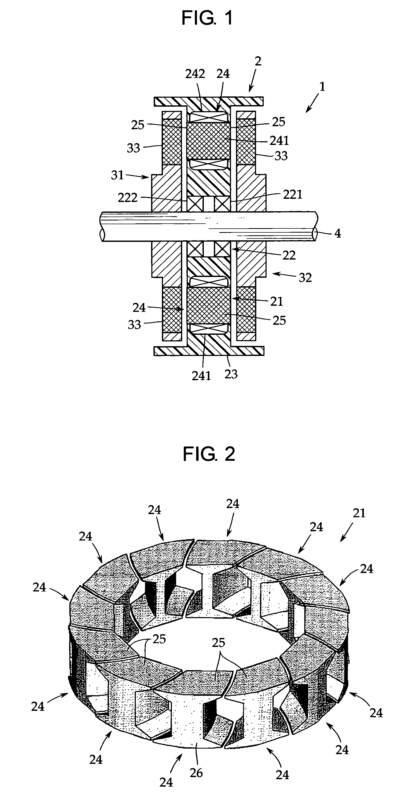
[0030]An embodiment of the present invention will now be described with reference to the accompanying drawings. FIG. 1 is a sectional view of a principal portion of an axial gap electronic motor in accordance with one embodiment of the present invention.

[0031]This axial gap electronic motor 1 has a stator 2 formed in a disc shape and a pair of rotors 31 and 32 arranged opposedly on both side surfaces of the stator 2 with a predetermined gap provided between the stator and the rotor. The rotors 31, 32 are fixed coaxially to a rotor output shaft 4 for outputting a rotational driving force. In this embodiment, the axial gap electronic motor 1 is a permanent magnet motor in which the rotors 31 and 32 each have a permanent magnet 33.

[0032]In this embodiment, the rotors 31, 32 are arranged on both sides of the stator 2, but it may be arranged either one side thereof. In the present invention, the configuration of the rotors 31, 32 is arbitrary, so that the explanation thereof is omitted.

[...


PUM


Abstract

An axial gap electronic motor includes a stator having a plurality of poles, and a rotor. Each pole is formed of a stator iron core made of a magnet body and a coil wound therearound. The rotor has a plurality of poles formed of permanent magnet and arranged along a rotation axis direction of said rotor with a predetermined gap provided therebetween. The stator has a magnetic force generating section in which a plurality of the stator iron cores is arranged in a ring shape on a concentric circle with the rotation axis line of the rotor being a center axis. Each of teeth of the stator iron core is provided with a skew.

Description

TECHNICAL FIELD[0001]The present invention relates to an axial gap electronic motor in which a stator and a rotor are arranged opposedly along the axial direction of an output shaft. More particularly, it relates to a stator iron core structure capable of decreasing cogging torque.BACKGROUND ART[0002]In an axial gap electronic motor, as disclosed in, for example, Patent Document 1 (Japanese Patent Application Publication No. 2000-253635), a rotor and a stator are arranged opposedly along the axial direction of an output shaft with a predetermined gap provided therebetween. The axial gap electronic motor can be designed so as to be thin as compared with the ordinary motor. For this reason, the motor of this type is preferably used as a hub motor for a power assisted bicycle, a driving motor for an FD drive, and the like.[0003]In a brushless motor made up of a stator iron core made of a magnetic material and a magnet rotor, when the magnetic resistance between the rotor and the stator...

Claims


Application Information

Patent Timeline
Patent Type & Authority Patents(United States)
IPC IPC(8): H02K1/00H02K1/06H02K1/12H02K21/24H02K29/03
CPCH02K29/03H02K21/24H02K1/2793H02K16/02H02K2213/03H02K2201/06
Inventor YAMADA, MASAKIIGARASHI, HISAONARITA, KENJIFUJIOKA, TAKUSHIKOJIMA, TOMONORIKATAGIRI, SHINICHIROYAMADA, SHINICHITANABE, YOICHITERAKUBO, HIDETAKASHINOHARA, TAKAYUKI
Owner FUJITSU GENERAL LTD
Why Eureka
Try Eureka