Ultrasonic surgical instrument

a surgical instrument and ultrasonic technology, applied in the field of ultrasonic surgical instruments, can solve the problems of difficult sterilization of instruments after use, enhanced power loss at couplings and seals of instruments, and mechanical faults in instruments

Inactive Publication Date: 2018-07-17
TYCO HEALTHCARE GRP LP
View PDF54 Cites 167 Cited by
  • Summary
  • Abstract
  • Description
  • Claims
  • Application Information

AI Technical Summary

Problems solved by technology

Further, power losses are enhanced at couplings and seals of the instrument.
Moreover, contact between the vibration coupler and stationary components of the instrument result in mechanical faults in the instrument.
Finally, the vibration coupler acts as a pump which draws bodily fluids from the distal end of the instrument to the proximal end of the instrument thereby making sterilization of the instrument after use difficult.
The use of an elongated vibration coupler also limits the operational features of the instrument available to a surgeon.
More specifically, because the vibration coupler transmits vibrations from the transducer to the end effector, the inclusion of an articulation joint into the vibration coupler is difficult and inefficient.
Any transverse vibrations that do occur as the energy is transmitted along the length of the vibration coupler reduces the overall efficiency of the system.

Method used


Image

  • Ultrasonic surgical instrument
  • Ultrasonic surgical instrument
  • Ultrasonic surgical instrument

Examples


Embodiment Construction

[0029]Preferred embodiments of the presently disclosed ultrasonic surgical instrument will now be described in detail with reference to the drawings, in which like reference numerals designate identical or corresponding elements in each of the several views.

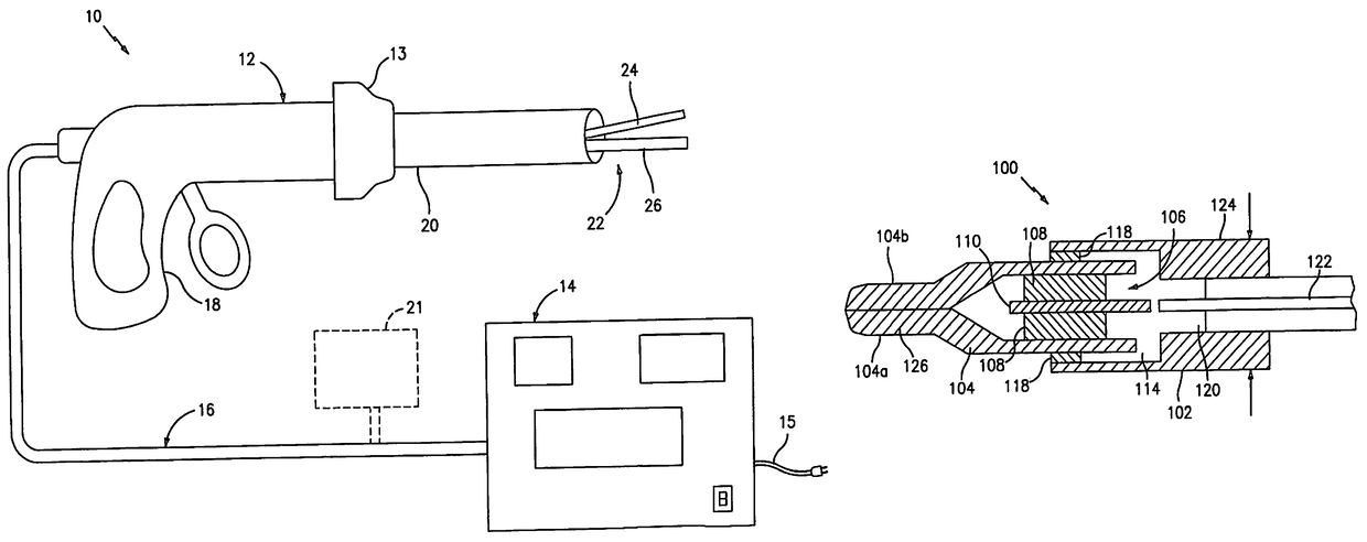
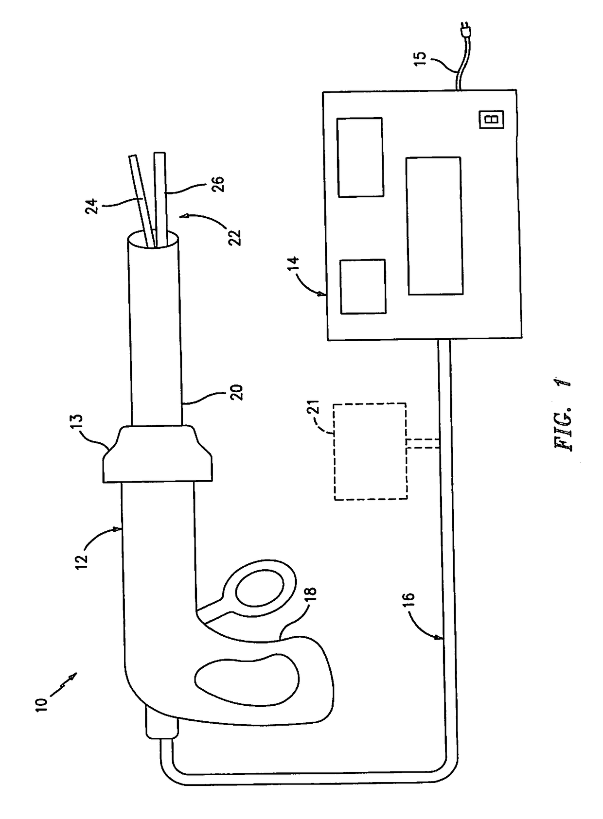
[0030]FIG. 1 illustrates a schematic view of an ultrasonic surgical system shown generally as 10. System 10 includes an ultrasonic instrument 12, a control module 14 and conductive cable 16 interconnecting instrument 12 to control module 14. Ultrasonic instrument 12 may be configured for open, endoscopic or laparoscopic surgical procedures and includes a handle assembly 18, an elongated body 20 and an end effector 22. Handle assembly 12 may have a pistol grip configuration, although other handle configurations are envisioned, e.g., in-line handle, pencil grips, standard scissor grips, new ergonomically designed grips, etc. Rotation knob 13 may be provided to facilitate rotation of elongated body 20 in a known manner. End effector...


PUM


Abstract

An ultrasonic surgical instrument is provided which includes a handle assembly, a body extending distally from the handle assembly and an end effector configured to effect cutting, dissection, coagulation and / or ligation of tissue. The end effector includes an ultrasonic member. A transducer is supported adjacent, on or within the ultrasonic member and is connected to a power source. Upon actuation of the power source, the transducer effects vibration of the ultrasonic member. In one preferred embodiment, the end effector is mounted for articulation about the distal end of the instrument.

Description

CROSS-REFERENCE TO RELATED APPLICATIONS[0001]This is a continuation of U.S. patent application Ser. No. 12 / 053,113, filed Mar. 21, 2008, (now abandoned), which is a continuation of U.S. patent application Ser. No. 10 / 467,512, filed Aug. 7, 2003 (now Abandoned), which is a 371 of PCT Patent Application Serial No. PCT / US2002 / 04988, filed Feb. 8, 2002, which claims priority to U.S. Provisional Application Ser. No. 60 / 267,251, filed Feb. 8, 2001, which is incorporated herein by reference in its entirety.BACKGROUND[0002]Technical Field[0003]The present disclosure relates generally to ultrasonic surgical instruments. More specifically, the present disclosure relates to ultrasonic surgical instruments having an end effector configured to effect tissue dissection, cutting, coagulation, ligation and / or hemostatis and having a microelectromechanical system incorporated therein (“MEMS”), which instrument can be used in open as well as laparoscopic or endoscopic surgical procedures.[0004]Backgr...

Claims


Application Information

Patent Timeline
Patent Type & Authority Patents(United States)
IPC IPC(8): A61B17/32A61B17/22A61B17/29A61B17/00A61B18/00A61B17/28
CPCA61B17/320068A61B17/29A61B17/320092A61B17/2202A61B2017/320072A61B2017/00084A61B2017/2927A61B2017/320071A61B2017/00026A61B2017/320069A61B2017/320094
Inventor ARANYI, ERNESTCUNY, DOUGLAS J.HEINRICH, RUSSELLLAL, AMITLEWIS, BILLROY, PHILIP C.
Owner TYCO HEALTHCARE GRP LP
Why Eureka
Try Eureka