Solar panel deployment system

a solar panel and deployment system technology, applied in the field of solar energy, can solve the problems of affecting the widespread use of solar panels in the field, the harsh military environment to which solar panels are exposed, and the impedement of solar panel deployment. the effect of safe transportation, fast and easy deployment, and rugged and durabl

Active Publication Date: 2018-07-17
THE UNITED STATES OF AMERICA AS REPRESENTED BY THE SECRETARY OF THE NAVY
View PDF61 Cites 10 Cited by
  • Summary
  • Abstract
  • Description
  • Claims
  • Application Information

AI Technical Summary

Benefits of technology

[0008]According to typical inventive practice, the present invention represents a rapidly deployable solar collection device that uniquely incorporates shipping and packaging into function. The present invention provides a solar energy collection device that is...

Problems solved by technology

A major obstacle to utilizing this free source of energy is the harsh military environment to which delicate (e.g., silicon-based) solar panels are to be exposed.
The widespread u...

Method used


Image

  • Solar panel deployment system
  • Solar panel deployment system
  • Solar panel deployment system

Examples


Embodiment Construction

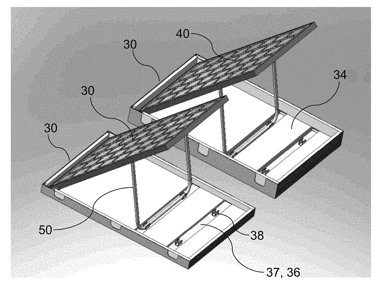
[0019]Referring now to the figures, the present invention's solar collection device, as typically embodied, includes a case 30, two solar panels 40, and two U-shaped bars 50. As shown in FIGS. 8 and 9, the case 30 includes and is separable into a pair of complementary main parts 31, viz., 31a and 31b, referred to herein as “compartments” or “open case components” or “semi-case components” or “half-case components.” The open case components 31 are attachable to and detachable from each other and represent halves or semi-sections of the case 30. The terms “half” and “semi” as used herein to refer to the present invention's open case components are not intended to suggest that two joinable components necessarily are congruent or equally dimensioned, but rather to suggest that, according to typical inventive practice, they are major, comparable, and complementary components.

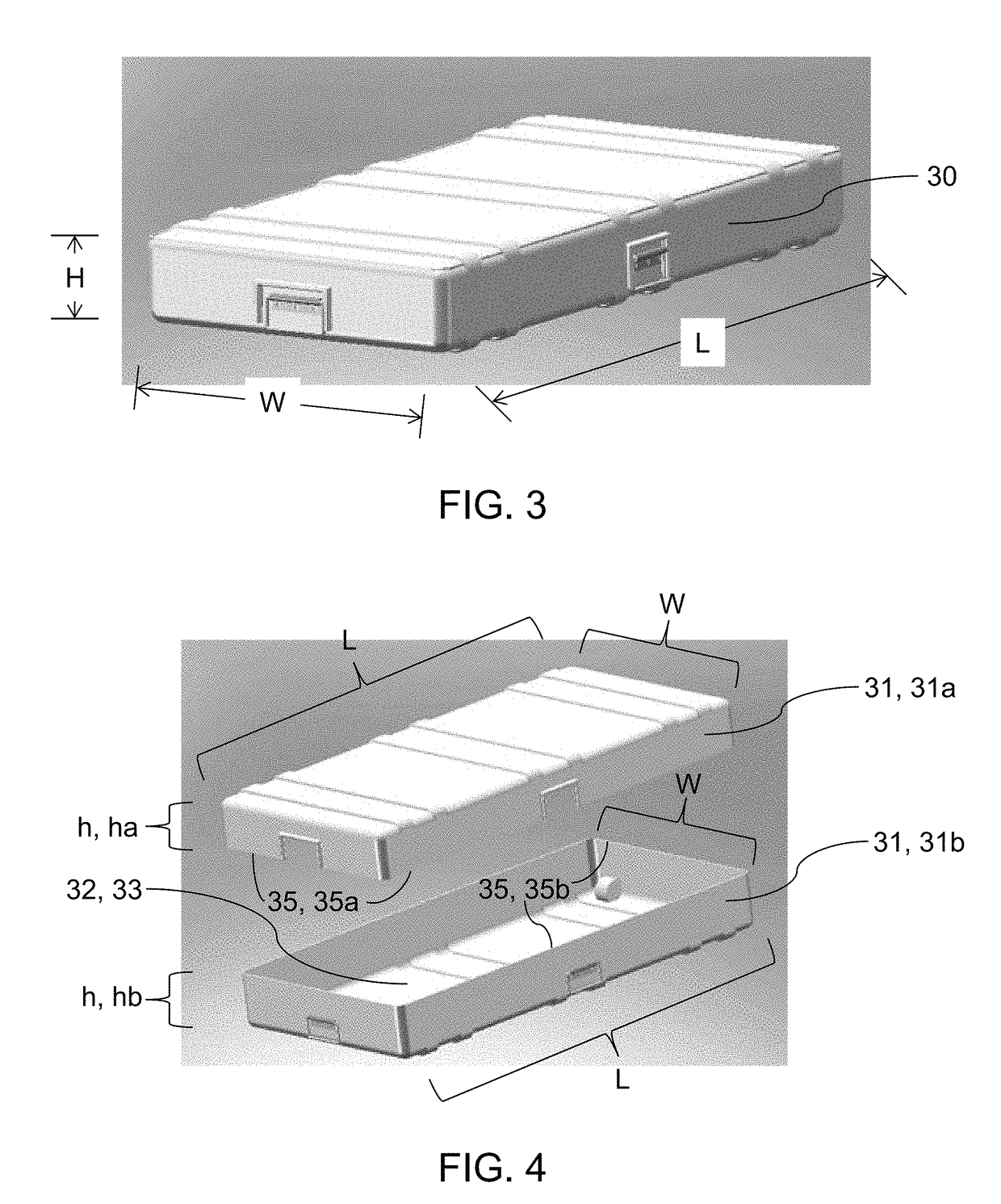
[0020]Particularly with reference to FIGS. 1 through 9, case 30 describes a rectangular parallelepiped and has len...


PUM


Abstract

The present invention typically features integrative configurability for transportation/storage, and disintegrative configurability for operation. Two half-cases are coupled to obtain a case. A case is uncoupled to obtain two half-cases. Each half-case houses a solar panel (pivotably connected to the half-case) and a U-bar (pivotably connected to the solar panel). The solar panel is pivoted away from the half-case's interior to the angle-of-inclination desired for collecting solar energy. The U-bar is pivoted away from the solar panel's back to securely fit into one of plural parallel slots provided across the half-case's interior, the U-bar thereby holding the solar panel in place at the desired angle-of-inclination. The half-cases are laid flat individually to collect solar energy. A half-case is “compacted” by pivoting the U-bar proximate the solar panel's back and pivoting the solar panel proximate the half-case's interior. Two complementary half-cases, each compacted, are (re)attached to form a portable case.

Description

CROSS-REFERENCE TO RELATED APPLICATIONS[0001]This application claims the benefit of U.S. provisional application No. 61 / 300,383, filed 1 Feb. 2010, hereby incorporated herein by reference, entitled “Solar Panel Deployment System,” joint inventors Clint Justin Govar, Evan Thomas Rule, Eric Bennet Shields, Anthony C. Suggs, and Richard Patrick Hardy.BACKGROUND OF THE INVENTION[0002]The present invention relates to solar energy, more particularly to methods and devices for collecting solar energy, such as involving use of solar panels for photovoltaically generating electricity.[0003]The military has considered implementing renewable energy systems to mitigate risk and to reduce logistical fuel burdens on deployed troops. Solar power has been regarded as a prime candidate as a renewable energy source that is capable of being readily deployed and of significantly ameliorating demand for logistical fuel. A major obstacle to utilizing this free source of energy is the harsh military envir...

Claims


Application Information

Patent Timeline
IPC IPC(8): F24S80/40
CPCF24S80/00F24S20/50F24S25/10F24S25/70H02S10/40H02S20/30Y02B10/10Y02B10/20Y02E10/47Y02E10/50H01L31/042H02S30/10H02S30/20
Inventor GOVAR, CLINT JUSTINRULE, EVAN THOMASSHIELDS, ERIC BENNETSUGGS, ANTHONY C.HARDY, RICHARD PATRICK
Owner THE UNITED STATES OF AMERICA AS REPRESENTED BY THE SECRETARY OF THE NAVY
Why Eureka
Try Eureka