Simulation tool for damage in composite laminates

a composite laminate and simulation tool technology, applied in the field of simulation tools for damage in composite laminates, can solve the problems of inability to use existing tools outside of research or academic type environments, inability to meet the needs of users, etc., to achieve low fidelity, computational efficiency, and easy use

Active Publication Date: 2018-07-31
NASA
View PDF10 Cites 0 Cited by
  • Summary
  • Abstract
  • Description
  • Claims
  • Application Information

AI Technical Summary

Benefits of technology

[0005]One aspect of the present invention is a numerical simulation tool for progressive damage in laminates. The simulation tool may utilize several numerical techniques (i.e., Floating Node Method (FNM), Virtual Crack Closure Technique (VCCT), finite element analysis) in connection with a developmental damage simulation theory in a manner necessary to fully capture the formation of a three dimensional internal crack network in a laminate using a model composed of a low fidelity mesh of planar type finite elements (i.e., a shell element, a plate element, or similar finite element). Shell / plate elements are general in nature, easily usable, and computationally efficient. The model mesh remains low fidelity throughout an analysis and increases in fidelity only locally as needed to suit a damage process occurring throughout a solution procedure.
[0011]The invention may be utilized to simulate damage in composite laminate structures in various applications, including the fields of aerospace, automobile and marine industries. The invention may be useful for a structure design and certification by simulating impact damage, compression after impact damage, or any similar delamination driven damage process in a laminate. For example, the simulation tool of the present invention may be utilized to evaluate various composite laminates. A structural component for an aircraft, vehicle, space craft, ship, etc. may be designed based, at least in part, on the results provided by the simulation tool. More specifically, a composite laminate having acceptable resistance to damage (delamination matrix cracking, etc.) may be selected for a structural component of an aircraft or other vehicle using the simulation tool of the present invention, and a composite laminate having a ply orientation etc. as evaluated / selected using the simulation tool may be utilized in fabricating the component. The simulation tool of the present invention may reduce the need to fabricate and test various laminates during the design process, and also utilizes significantly less computer resources than prior multi-layer finite element methods utilized for damage simulation / evaluation of composite materials.

Problems solved by technology

Damage processes in laminates can be inherently complex.
A primary disadvantage of prior high fidelity simulation models is that they can be cost inhibitive in terms of required user expertise, model development time, and computational resources.
Often existing tools are not feasible for use outside of research or academic type environments because, even for consideration of a simple damage process in small structures, their use requires a high level of training and time.
Furthermore, if a model becomes too high fidelity and involves too many interacting damage processes, there are more sources for error to appear and magnify.

Method used


Image

  • Simulation tool for damage in composite laminates
  • Simulation tool for damage in composite laminates
  • Simulation tool for damage in composite laminates

Examples


Embodiment Construction

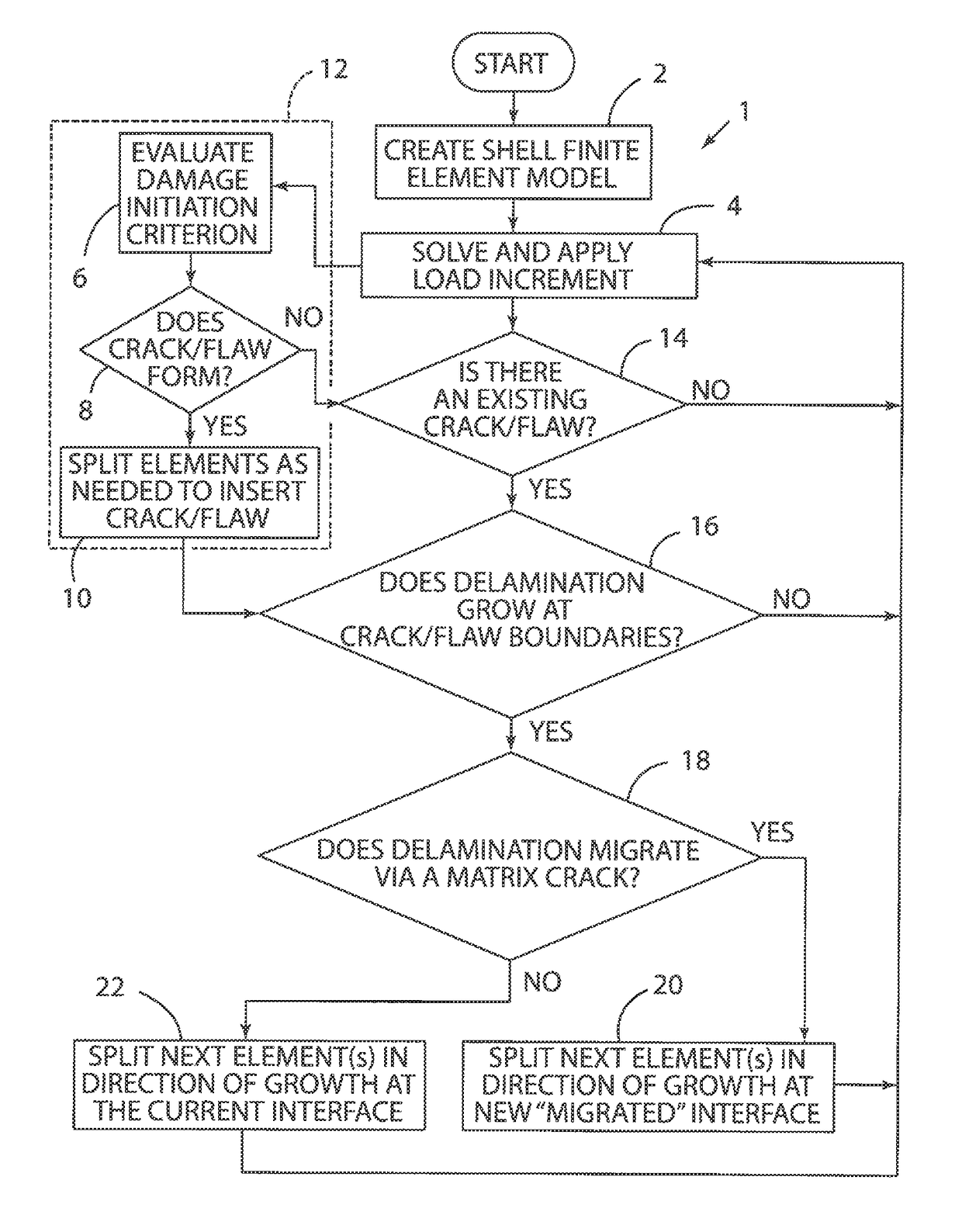
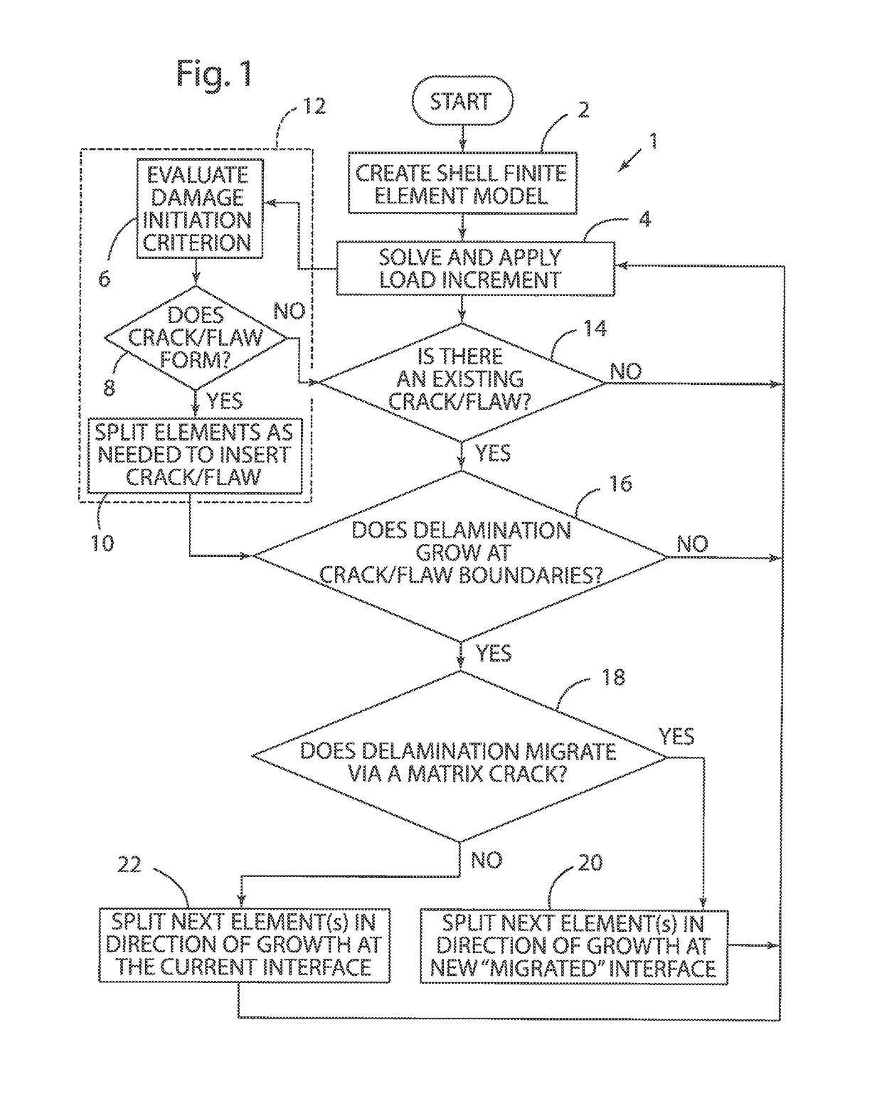
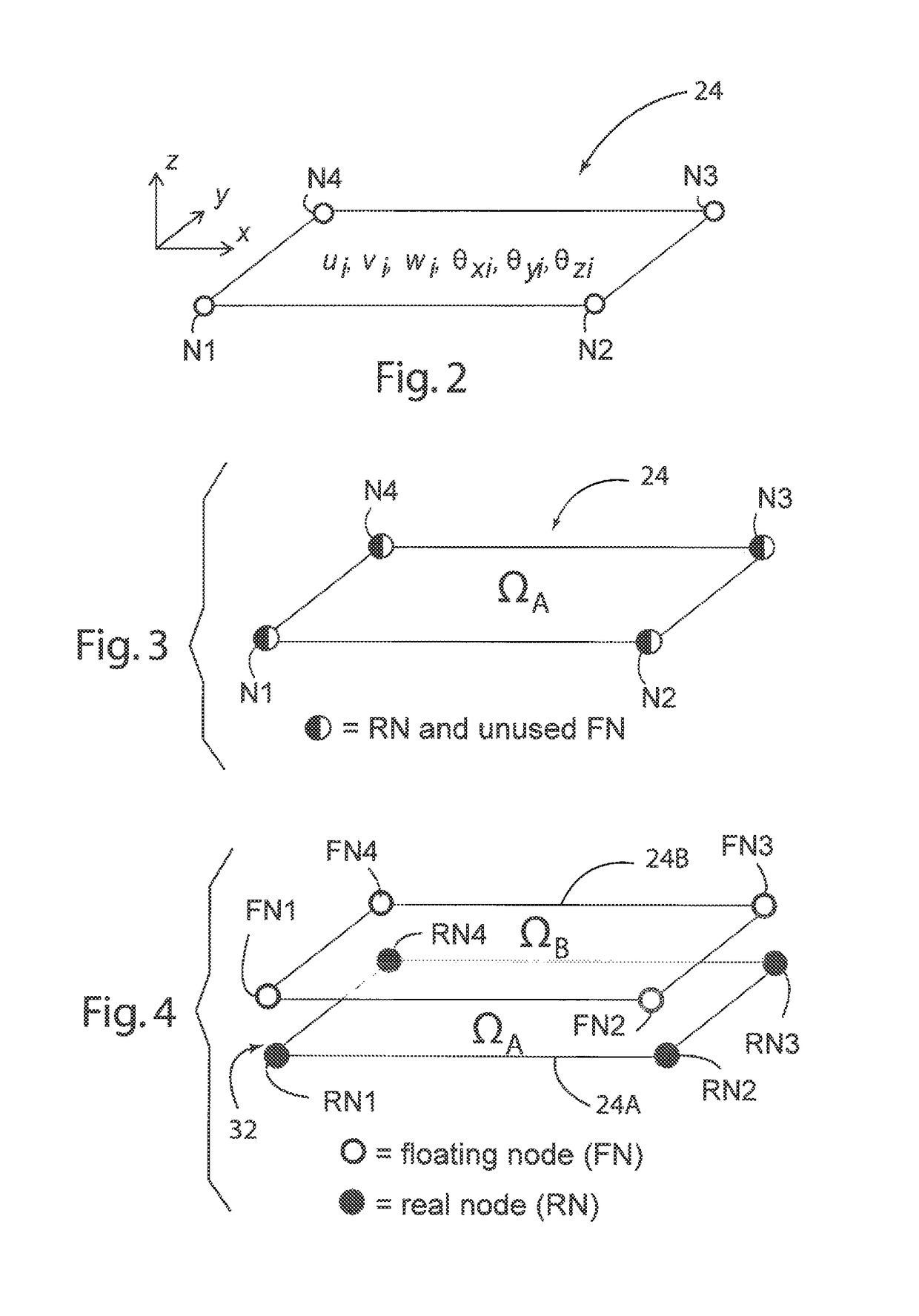
[0023]For purposes of description herein, the terms “upper,”“lower,”“right,”“left,”“rear,”“front,”“vertical,”“horizontal,”“positive,”“negative,” and derivatives thereof shall relate to the invention as oriented in FIG. 2. A summary of the process is shown in FIG. 1. However, it is to be understood that the invention may assume various alternative orientations and step sequences, except where expressly specified to the contrary. It is also to be understood that the specific devices and processes illustrated in the attached drawings, and described in the following specification, are simply exemplary embodiments of the inventive concepts defined in the appended claims. Hence, specific dimensions and other physical characteristics relating to the embodiments disclosed herein are not to be considered as limiting, unless the claims expressly state otherwise.

[0024]FIG. 1 depicts a process 1 according to one aspect the present invention. Following the start of process 1, a shell finite elem...


PUM

PropertyMeasurementUnit
stiffnessaaaaaaaaaa
finite element solutionaaaaaaaaaa
incremental finite element load step solutionaaaaaaaaaa

Abstract

A numerical simulation tool for progressive failure in laminates utilizes a low fidelity approach. The numerical model includes an enriched element that is initially in a low fidelity form. The enriched elements may increase fidelity by splitting locally to simulate an ongoing damage process such as delamination.

Description

CROSS-REFERENCE TO RELATED PATENT APPLICATIONS[0001]This patent application claims the benefit of and priority to U.S. Provisional Patent Application No. 62 / 166,319, titled “SIMULATION TOOL FOR DAMAGE IN COMPOSITE LAMINATES” filed on May 26, 2015; U.S. Provisional Patent Application No. 62 / 087,841, titled “SIMULATION TOOL FOR DAMAGE IN COMPOSITE LAMINATES” filed on Dec. 5, 2014; and U.S. Provisional Patent Application No. 62 / 079,182, titled “SIMULATION TOOL FOR DAMAGE IN COMPOSITE LAMINATES” filed on Nov. 13, 2014. The entire contents of each of the above-identified provisional applications are hereby incorporated by reference in their entirety.STATEMENT REGARDING FEDERALLY SPONSORED RESEARCH OR DEVELOPMENT[0002]The invention described herein was made by an employee of the United States Government and may be manufactured and used by or for the Government of the United States of America for governmental purposes without the payment of any royalties thereon or therefore.BACKGROUND OF ...

Claims


Application Information

Patent Timeline
Patent Type & Authority Patents(United States)
IPC IPC(8): G01N19/08G01N3/00
CPCG01N19/08G01N3/00G01N2203/0216G01N2203/0066G01N2203/0212G01N2203/0025G01N2203/0062
Inventor MCELROY, MARK W.
Owner NASA
Why Eureka
Try Eureka