Warm white LED spectrum especially for retail applications

a led spectrum and retail technology, applied in lighting applications, lighting support devices, lighting and heating apparatuses, etc., can solve the problems of lagging efficiency, color and white perception, general acceptance of led solutions, etc., and achieve good efficiency

Active Publication Date: 2022-01-04
SIGNIFY HLDG BV
View PDF13 Cites 0 Cited by
  • Summary
  • Abstract
  • Description
  • Claims
  • Application Information

AI Technical Summary

Benefits of technology

[0011]Key for adoption of alternative lighting devices seem a high efficiency (especially >100 lm / W) and a high color rendering (especially CRI≥90) and optimal white perception (which is achieved in WO2013 / 150470 by excitation of optical brightness agents via the deep blue wavelengths in the lamp emission spectrum).
[0013]A breakthrough in LED lighting for Retail has been the invention of Crisp White in WO2013 / 150470 (see also above). The addition of a deep blue emission peak excites the optical brightening agents, present in white fabrics, paint and plastics. That results in a strongly improved whiteness perception. This Crisp White source is accepted in the market as the replacement of CDM in terms of whiteness and color rendering.
[0035]As indicated above, the procedure for calculating the relative gamut area index (Ga) is described. It should best be used in conjunction with Ra to indicate the origin for a lower fidelity score, i.e., larger or smaller color gamut compared to the reference source. However, also Ga summarizes all color shifts into one single number, whereas a relatively small shift for a specific color may be more important for a specific application than relatively larger shifts for other colors. A graphical representation provides a comprehensive overview on the changes in colorfulness and hue shifts for all individual colors used to determine index values Ra and Ga. It is supplementary and helps in making more informed design decisions.
[0044]Hence, it is an aspect of the invention to provide an alternative lighting device, which preferably further at least partly obviates one or more of above-described drawbacks, which especially has a relative high efficiency, a relative high CRI, a high Ga (GAI), a good color rendering and some saturation of one or more colors.
[0046]It was surprisingly found that by shifting the blue peak in the white spectrum to shorter wavelength one or more of a good white ‘rendering’, a high gamut area index (sometimes also indicated as color saturation index), a perception as CDM-elite, and a good efficiency is obtainable. This can be realized in various manners: tuning the blue LED wavelength and / or tuning the absorption of the (green) phosphor.
[0052]Especially, the first luminescent material light (211) has an intensity in one or more of the green and yellow having a CIE u1′, and the second luminescent material light (221) has an intensity in one or more of the orange and red having a CIE u2′, wherein the first luminescent material (210) and the second luminescent material (220) are selected to provide said first luminescent material light (211) and said second luminescent material light (221) defined by a maximum ratio of CIE u1′ (211) and CIE u2′ (221) being CIE u2′ (221)=1.58*CIE u1′ (211)+0.255, and a minimum ratio of CIE u1′ (211) and CIE u2′ (221) being CIE u2′ (221)=2.3*CIE u1′ (211)+0.04. It appears that when one or more luminescent materials are chosen that comply with these conditions, i.e. have a ratio defined by these equations or have a value between these maximum and minimum ratio's, provide especially the desired optical properties of e.g. CIE and GAI, and may provide lighting devices having a good efficiency.

Problems solved by technology

However, general acceptance of these LED solutions has been hampered by lagging of efficiency, color and white perception.

Method used


Image

  • Warm white LED spectrum especially for retail applications
  • Warm white LED spectrum especially for retail applications
  • Warm white LED spectrum especially for retail applications

Examples


Embodiment Construction

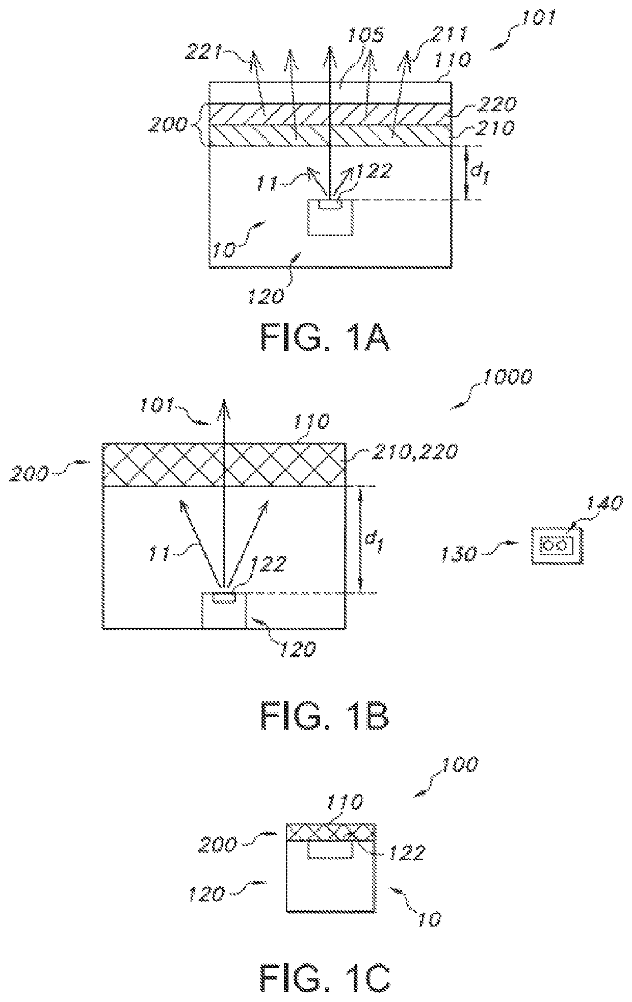
[0132]FIG. 1a schematically depicts an embodiment of a lighting device 100 as described herein. The lighting device 100 comprises a light source 10 configured to provide blue light source light 11, a first luminescent material 210 configured to convert at least part of the light source light 11 into first luminescent material light 211 with light intensity in one or more of the green spectral region and yellow spectral region and a second luminescent material 220 configured to convert (i) at least part of the light source light 11, or (ii) at least part of the light source light 11 and at least part of the first luminescent material light 211 into second luminescent material light 221 with light intensity in the orange and / or red spectral region.

[0133]Further, the lighting device comprises a light exit face 110. Herein in the embodiment of FIG. 1a, this may be the downstream face of a window 105.

[0134]The terms “upstream” and “downstream” relate to an arrangement of items or feature...


PUM

PropertyMeasurementUnit
peak wavelengthaaaaaaaaaa
CRIaaaaaaaaaa

Abstract

The invention provides a lighting device (100) configured to provide lighting device light (101), the lighting device (100) comprising a solid state light source (10) configured to provide blue light (11) having a peak wavelength (λPWL) selected from the range of 430-455 nm, a first luminescent material (210) configured to convert part of the blue light (11) into first luminescent material light (211) and a second luminescent material (220) configured to convert part of one or more of the blue light (11) and the first luminescent material light (211) into second luminescent material light (221), wherein the solid state light source (10), the first luminescent material (210), and the second luminescent material (220) are selected to provide at a first setting of the lighting device (100) white lighting device light (101) having a CRI of at least 90, a R9 value of at least 70, and a R50 value of at maximum 465 nm, wherein the R50 value is defined as a first wavelength (λ50) in a spectral distribution of the white lighting device light (101) at the first setting, wherein the first wavelength (λ50) is a wavelength closest to the peak wavelength (λPWL) but at a longer wavelength than the peak wavelength (λPWL) of the blue light (11) where the peak intensity (I50) is 50% of the intensity (IPWL) at the peak wavelength (λPWL).

Description

CROSS-REFERENCE TO PRIOR APPLICATIONS[0001]This application is the U.S. National Phase application under 35 U.S.C. § 371 of International Application No. PCT / EP2018 / 060707, filed on Apr. 26, 2018, which claims the benefit of European Patent Application Nos 17168963.1, filed on May 2, 2017 and 17169476.3, filed on May 4, 2017. These applications are hereby incorporated by reference herein.FIELD OF THE INVENTION[0002]The invention relates to a lighting device, a lighting system comprising such lighting device, as well as the use of such lighting device.BACKGROUND OF THE INVENTION[0003]White lighting devices are known in the art. WO2013 / 150470, for instance, describes a light emitting module adapted to produce white output light having an emission peak in the wavelength range from 400 to 440 nm, which comprises at least one first light emitting element adapted to emit light having an emission peak in a first wavelength range from 440 to 460 nm, at least one wavelength converting materi...

Claims


Application Information

Patent Timeline
Patent Type & Authority Patents(United States)
IPC IPC(8): F21V21/00F21V9/38F21K9/64C09K11/08C09K11/77C09K11/89F21Y115/10F21W131/405
CPCF21V9/38C09K11/0883C09K11/7734C09K11/89F21K9/64F21W2131/405F21Y2115/10H01L33/50C09K11/77348Y02B20/00
Inventor PEETERS, MARTINUS PETRUS JOSEPHWEGH, RENE THEODORUS
Owner SIGNIFY HLDG BV
Why Eureka
Try Eureka