Electronic control unit

a control unit and electronic technology, applied in the direction of braking systems, electric devices, braking components, etc., can solve the problems of high power consumption, high accuracy, and incorrect detection of the state of the monitor target, and achieve high accuracy, high accuracy, and high accuracy.

Active Publication Date: 2018-08-07
DENSO CORP
View PDF14 Cites 1 Cited by
  • Summary
  • Abstract
  • Description
  • Claims
  • Application Information

AI Technical Summary

Benefits of technology

[0007]The present disclosure is made in view of the foregoing and has an object to provide an electronic control unit that can highly accurately detect and determine a state of a monitor target while minimizing power consumption.
[0009]This electronic control unit includes the first power supply and the second power supply having higher accuracy than the first power supply, as power supplies for supplying power to the sensor which detects the state of the monitor target. The controller performs the first determination using the lower accuracy first power supply. Thereafter, when determining the occurrence of the change in the state of the monitor target in the first determination, the controller switches the power supply into the high accuracy second power supply and then performs the second determination. Therefore, the state of the monitor target can be highly accurately detected as compared with a case where the monitoring is performed with only the first power supply. Additionally, although the use of a high accuracy power supply for monitoring may cause much more consumption than the use of a low accuracy power supply, the high accuracy power supply (second power supply) is used when the first determination determines the occurrence of the change in the present disclosure. Therefore, the power consumption can be suppressed as compared with a case where the high accuracy power supply is always used.

Problems solved by technology

In this case, if accuracy of the reference voltage, that is, accuracy of a power supply which supplies the reference voltage, is low, the state of the monitor target may be wrongly detected.
Additionally, when the wakeup cycle is shorted in order to improve the detection accuracy as is the case in the method of Patent Literature 1, the power consumption may increase.
Additionally, although the use of a high accuracy power supply for monitoring may cause much more consumption than the use of a low accuracy power supply, the high accuracy power supply (second power supply) is used when the first determination determines the occurrence of the change in the present disclosure.

Method used


Image

  • Electronic control unit
  • Electronic control unit
  • Electronic control unit

Examples


Embodiment Construction

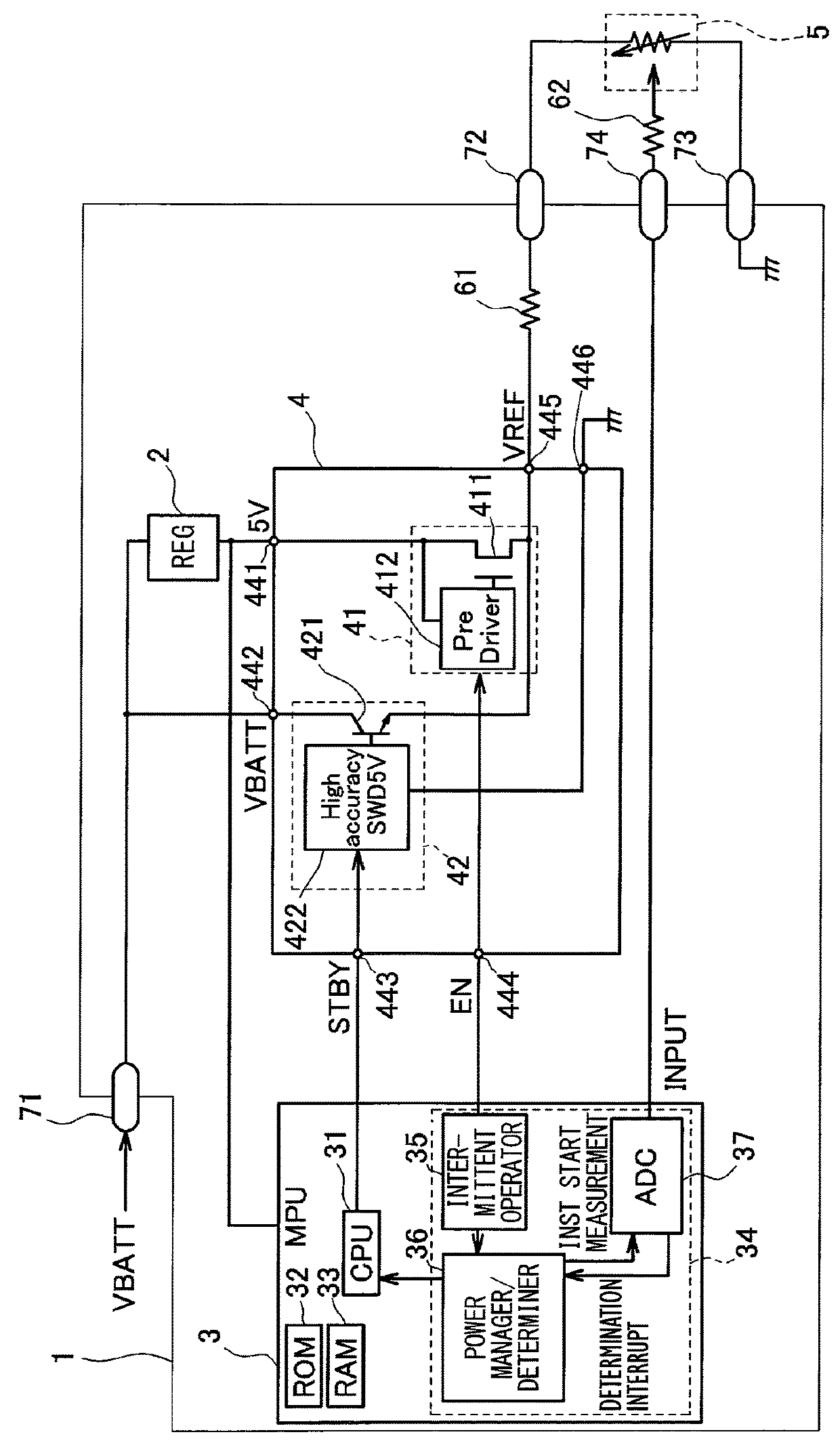
[0014]Embodiments will be described with reference to the drawings. FIG. 1 is a schematic diagram illustrating an in-vehicle system. The in-vehicle system of FIG. 1 is mounted to a vehicle 100 illustrated in FIG. 4. This in-vehicle system includes an ECU (Electronic Control Unit) 1 and a sensor 5.

[0015]The sensor 5 detects a state of a predetermined part of the vehicle 100. Specifically, the sensor 5 detects an operation (press down) of a brake pedal 50 (see FIG. 4) of the vehicle 100. The brake pedal 50 is provided in a driver's underfoot region of the vehicle 100 and acts as an operation part which the driver presses down with his foot in braking the vehicle 100. The sensor 5 includes a variable resistor whose resistance changes according to the position of the brake pedal 50. According to the resistance of the variable resistor, the sensor 5 (potentiometer) outputs an electrical signal (analog signal) as a signal indicating the position of the brake pedal 50. Specifically, the se...


PUM


Abstract

An electronic control unit monitors a state of a monitor target based on an analog signal from a sensor which is supplied with electric power and which outputs the analog signal that changes in accordance with a value of the electric power and the state of the monitor target. The electronic control unit includes a first power supply, a second power supply having higher accuracy than the first power supply, and a controller. The controller supplies the power to the sensor with the first power supply and determines whether there is a change in the state of the monitor target based on the analog signal. When determining that there is the change, the controller switches over a power supply from the first power supply to the second power supply and determines whether there is a change in the state of the monitor target.

Description

CROSS REFERENCE TO RELATED APPLICATIONS[0001]This application is a U.S. National Phase Application under 35 U.S.C. 371 of International Application No. PCT / JP2014 / 003969 filed on Jul. 29, 2014 and published in Japanese as WO 2015 / 029330 A1 on Mar. 5, 2015. This application is based on and claims the benefit of priority from Japanese Patent Application No. 2013-174666 filed on Aug. 26, 2013. The entire disclosures of all of the above applications are incorporated herein by reference.TECHNICAL FIELD[0002]The present disclosure relates to an electronic control unit that monitors a state of a monitor target.BACKGROUND ART[0003]An electronic control unit mounted to a vehicle, such as a body control ECU which controls electric components of a vehicle, transitions to a sleep state when an ignition key is OFF, a standby state. In the sleep state, functions of the electronic control unit are stopped to a maximum extent to minimize the power consumption of a battery. The electronic control un...

Claims


Application Information

Patent Timeline
Patent Type & Authority Patents(United States)
IPC IPC(8): B60L1/00B60L3/00H02G3/00B60R16/023B60T8/88B60T8/00B60R16/033
CPCB60R16/033B60R16/0236B60T8/885B60T8/00B60T2270/406
Inventor NISHIDA, MIYUKI
Owner DENSO CORP
Why Eureka
Try Eureka