
Sealing structure and pressure change detection device

a technology of sealing structure and detection device, which is applied in the direction of fluid pressure measurement using pistons, fluid pressure measurement using elastically deformable gauges, etc., can solve the problems of increasing the amount of compression corresponding to the sealing section, accompanied temporal deterioration, etc., and achieve excellent preventive

Active Publication Date: 2018-08-28
SEIKO EPSON CORP
View PDF4 Cites 0 Cited by
  • Summary
  • Abstract
  • Description
  • Claims
  • Application Information

AI Technical Summary

Benefits of technology

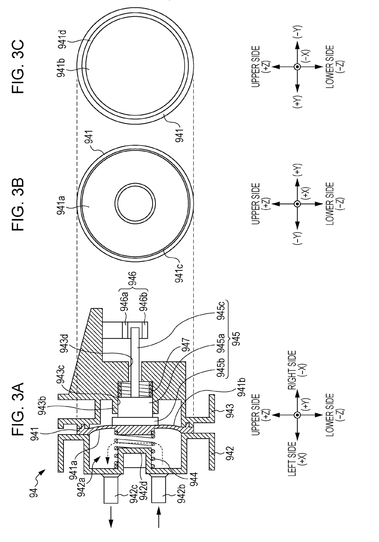
This patent describes a technology that prevents pressure leaks in a sealing structure. A displacement member is used that changes in pressure can displace. When sucking force is applied, the second projecting section comes into contact with the wall surface of the housing and receives reaction force, preventing deformation of the displacement member. This results in improved sealing performance and prevents leakage. When negative pressure is applied, the thickness of the displacement member increases and the amount of compression corresponding to the sealing section increases, further improving sealing performance. When sucking force stops, the displacement member becomes reduced, resulting in lower loads on the sealing section, preventing permanent deformation. The second projecting section should be formed on a surface opposite to the surface on which the first projecting section is formed to effectively prevent deterioration.

Problems solved by technology

In the device disclosed in JP-A-2000-211152, the displacement member comes into contact with ink, thereby accompanying temporal deterioration.
In addition, such a problem is not characteristic of the pressure change detection device, and may occur, for example, in the sealing structure of the ink supply device (liquid supply device) disclosed in JP-A-2010-23423.
In addition, when negative pressure is applied to the displacement member, the thickness of the first projecting section becomes thick, and thus the amount of compression corresponding to the sealing section increases.

Method used


Image

  • Sealing structure and pressure change detection device
  • Sealing structure and pressure change detection device
  • Sealing structure and pressure change detection device

Examples


Embodiment Construction

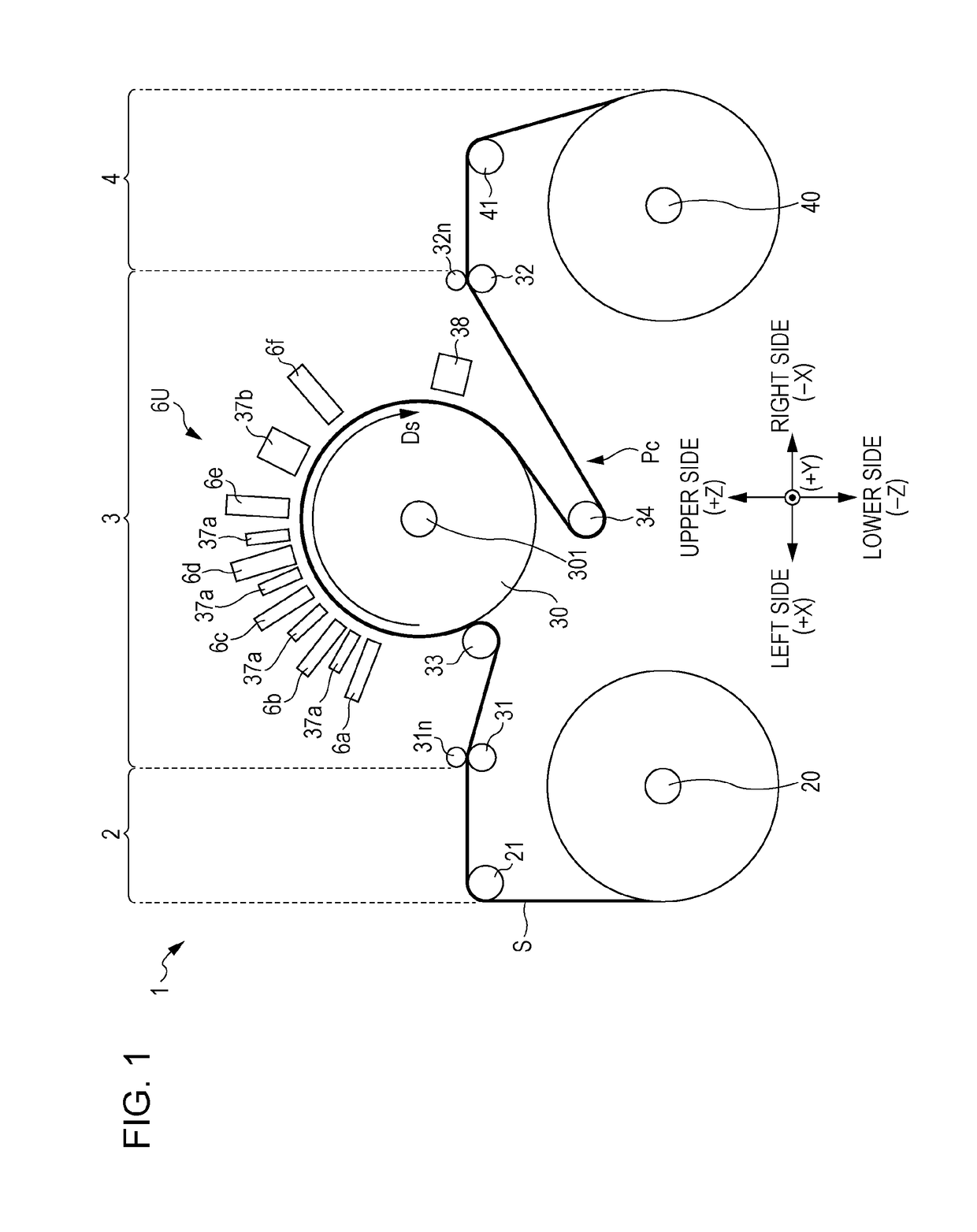
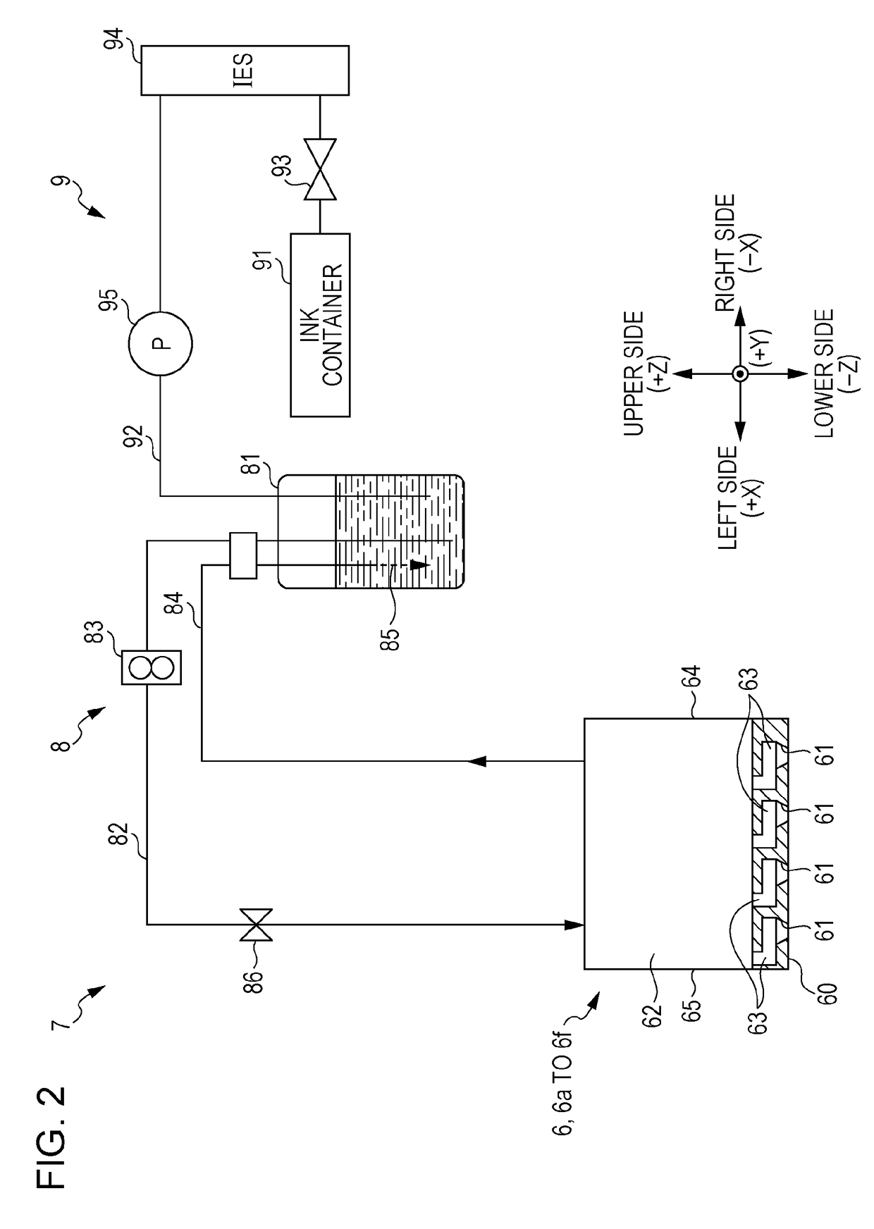
[0019]Hereinafter, the configuration of a printer which includes an ink end detection device that is an example of a pressure change detection device of the invention will be described with reference to the accompanying drawings. FIG. 1 is a front view schematically illustrating the configuration of a printer to which a pressure change detection device according to an embodiment of the invention can be applied. Meanwhile, in the drawings below, in order to make the relation of placement between the respective sections of the printer 1 clear, a 3-dimensional coordinate system, which includes the horizontal direction X, the front and rear direction Y, and the vertical direction Z of the printer 1, if necessary.

[0020]As illustrated in FIG. 1, in the printer 1, a delivery section 2, a process section 3, and a winding section 4 are arranged in the horizontal direction. The delivery section 2 and the winding section 4 respectively include a delivery shaft 20 and a winding shaft 40. Furthe...


PUM

PropertyMeasurementUnit
pressureaaaaaaaaaa
reaction forceaaaaaaaaaa
timeaaaaaaaaaa

Abstract

There is provided a sealing structure in which sealing is performed by covering a fluid passage of a housing using a displacement member that is displaceable according to change in pressure. The displacement member includes a first projecting section which is a sealing section in an outer peripheral section, and a second projecting section which is formed in an inner peripheral section rather than the first projecting section, and the housing is capable of fixing the displacement member in a state in which the first projecting section is compressed, and includes a depression section, in which the second projecting section is placed when the displacement member is fixed, in a position which faces the second projecting section.

Description

BACKGROUND[0001]1. Technical Field[0002]The present invention relates to a sealing structure in which a housing is sealed using a displacement member that is displaceable according to change in pressure, and a pressure change detection device which includes the sealing structure.[0003]2. Related Art[0004]For example, JP-A-2000-211152 discloses a device in which a pressure change detection device is used as an ink end detection device for detecting the ink end of a main tank. The pressure change detection device includes a flexible displacement member which forms a part of an ink supply path and which is displaceable according to a change in the pressure occurring in the path, a spring member which is attached to the displacement member and biases the displacement member in a direction opposite to the direction in which the displacement member is displaced according to a drop in pressure occurring in the path, and a displacement detection section which detects the displacement of the...

Claims


Application Information

Patent Timeline
Patent Type & Authority Patents(United States)
IPC IPC(8): G01L7/08G01L7/16
CPCG01L7/163
Inventor HAMAMOTO, SEIKO
Owner SEIKO EPSON CORP
Learn More