Image forming apparatus

a technology of image forming apparatus and forming chamber, which is applied in the direction of recording apparatus, inking apparatus, instruments, etc., can solve the problems of high flatness, high cost, and low consideration of the curvature of the mirror, so as to achieve the effect of easy settlement of the deflection of the optical characteristic valu

Inactive Publication Date: 2010-04-13
BROTHER KOGYO KK
View PDF13 Cites 0 Cited by
  • Summary
  • Abstract
  • Description
  • Claims
  • Application Information

AI Technical Summary

Benefits of technology

[0008]However, the mirror with high flatness has a deteriorated productivity incurring a high cost, and therefore using the mirror with high flatness leads to an increase of cost of the image forming apparatus.
[0009]Therefore, an object is to provide the image forming apparatus capable of excellently preventing the color slippage from occurring, without using the mirror with high flatness.
[0012]Although various selection methods of the mirror according to the aspect can be considered, but at least one or more of the mirrors are respectively provided on each of the light paths, and curvature of the reflective surface of each mirror may be entirely positive or entirely negative. In this case, the error of the scanning position is generated in the same direction on any light path. Therefore, the deflection of the optical characteristic value is easily settled in the determined range.

Problems solved by technology

However, in the aforementioned patent document, a curvature of mirror is not taken into consideration at all.
However, the mirror with high flatness has a deteriorated productivity incurring a high cost, and therefore using the mirror with high flatness leads to an increase of cost of the image forming apparatus.

Method used


Image

  • Image forming apparatus
  • Image forming apparatus
  • Image forming apparatus

Examples


embodiment 1

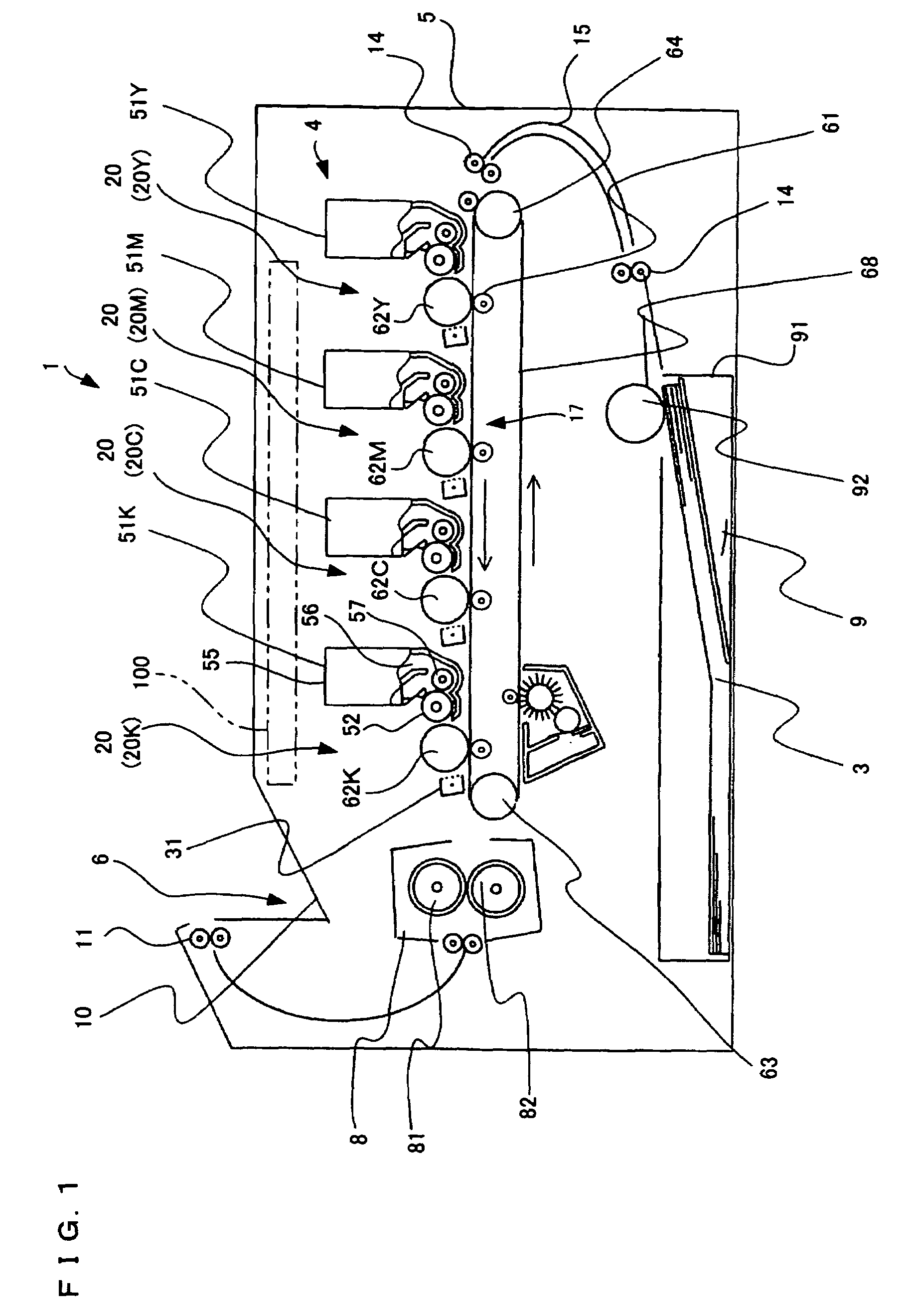
[0023]An embodiment will be explained based on the drawings hereafter. In FIG. 1, a printer 1 is a tandem-type color laser printer having four image forming units 20 as will be described later arranged horizontally in parallel with each other. A body casing 5 comprises a paper feeding section 9 for feeding recording sheet 3 as a medium to be recorded, an image forming section 4 for forming an image on the fed recording sheet 3, and a paper discharging section 6 for discharging the recording sheet 3 on which the image is formed.

[0024]The paper feeding section 9 has a paper feeding tray 91 installed removably from the front side (right side in FIG. 1) of the body casing 5, at a bottom portion in the body casing 5. Further, the paper feeding section 9 comprises a paper feeding roller 92 provided on a front upper side of the paper feeding tray 91, and carrying rollers 14 provided in an upper part of the paper feeding roller 92 and on a downstream side of the paper feeding roller 92 in t...

embodiment 2

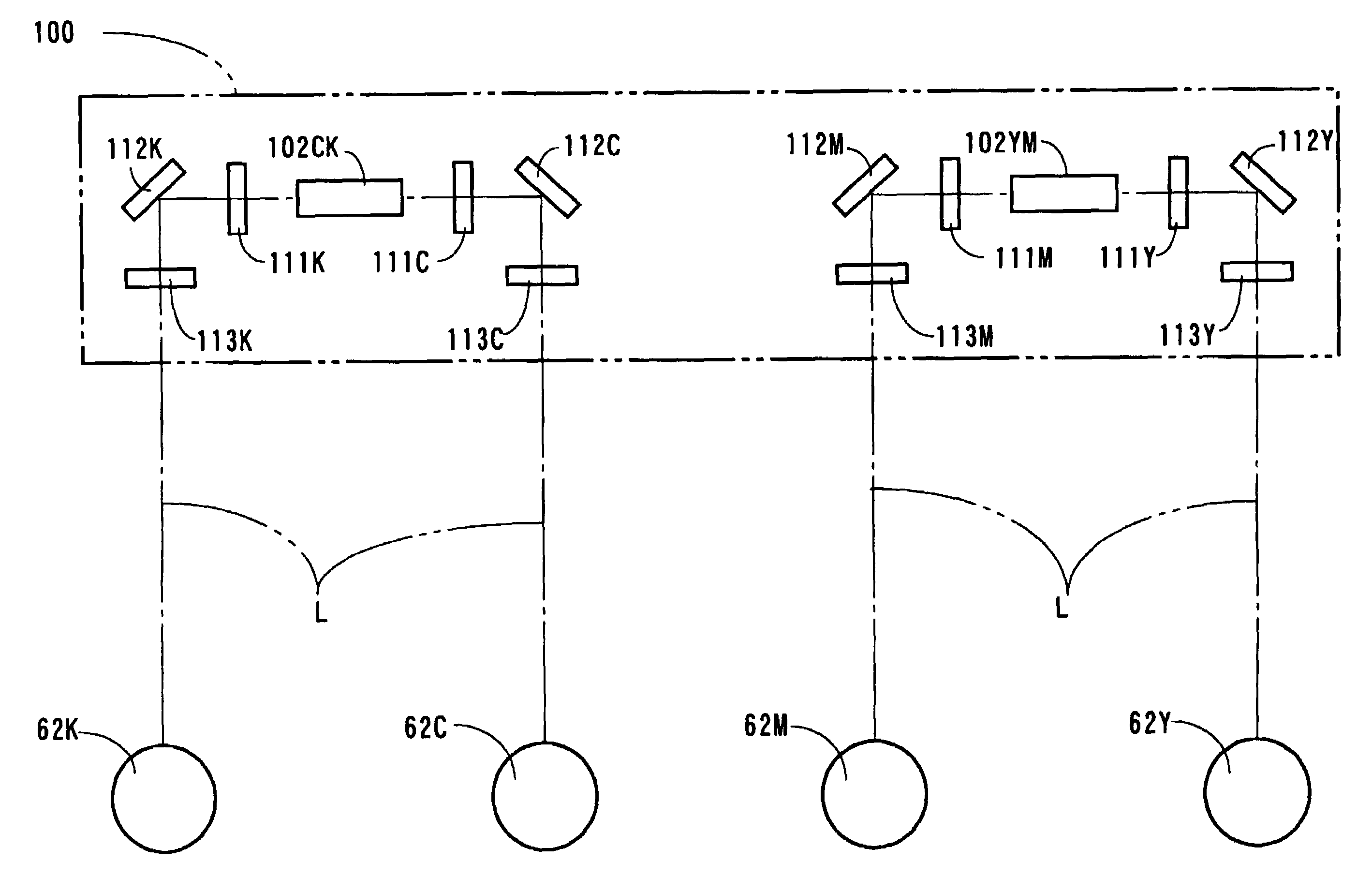
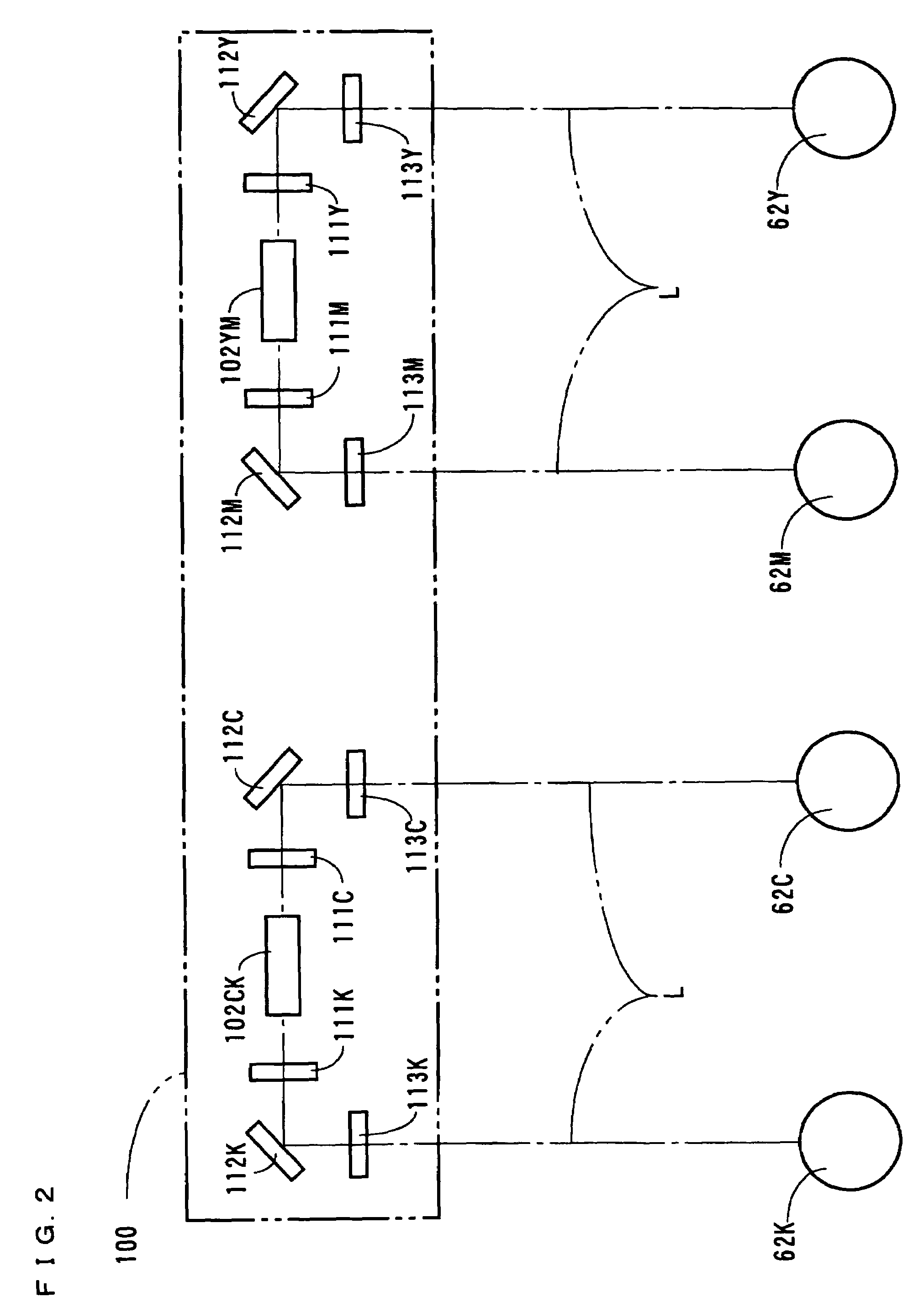
[0050]FIG. 5 is a sectional view showing the scanner unit 100 according to other embodiment. In this embodiment, the scanner unit 100 comprises only one polygon mirror 102 for scanning the laser beams L to which the photoreceptor drums 62Y, 62M, 62C, 62K are exposed. The place in the vicinity of the polygon mirror 102 has approximately the same constitution as the constitution shown in the embodiment 1 shown in FIG. 3. A different point is that, as shown in FIG. 6, the semiconductor laser 103Y and the collimate lens 104Y corresponding to yellow (Y) and the semiconductor laser 103M and the collimate lens 104M corresponding to magenta (M) are arranged in an overlaid state, and the semiconductor laser 103K and the collimate lens 104K corresponding to black (K) and the semiconductor laser 103C and the collimate lens 104C corresponding to cyan (C) are arranged in an overlaid state.

[0051]The laser beams L emitted from the semiconductor lasers 103Y and 103M are emitted to a common reflecti...

embodiment 3

[0057]FIG. 8 is a sectional view showing a schematic constitution of an embodiment wherein a polygon mirror 102 and an fθ lens 131 are used commonly in each color. According to this embodiment, a common reflective surface of the polygon mirror 102 is irradiated with four laser beams L corresponding to each color at different incident angles, from four overlapped semiconductor lasers and collimate lenses (not shown).

[0058]The laser beams L corresponding to each color are reflected by the aforementioned reflective surface of the polygon mirror 102 at different angles, and passed through a common fθ lens 131. Thereafter, the laser beams L corresponding to yellow (Y) are sequentially reflected by mirrors 132Y and 133Y, pass through a cylindrical lens 134Y, and reach the photoreceptor drum 62Y. The laser beams L corresponding to magenta (M) pass through the fθ lens 131, then are sequentially reflected by mirrors 132M and 133M, then pass through a cylindrical lens 134M, and reach the phot...


PUM


Abstract

To provide an image forming apparatus suppressing color slippage without using a mirror with high flatness, when a reflective surface of the mirror used in an optical system of, for example, yellow is formed in a completely flat surface, and a curvature R of the reflective surface of the mirror used in the optical system of magenta is +75 m, a deviation of a scanning position exceeds 100 μm at maximum, resulting in accentuating the color slippage. Meanwhile, when the mirror of yellow is replaced with the mirror having the curvature R of +300 m, the slippage can be suppressed to 100 μm or less. Therefore, each mirror is selected, so that the curvature of each mirror becomes all positive or all negative. Thus, the deviation of the scanning position is in the same direction of laser beams L of each color, and the slippage can be prevented.

Description

CROSS-REFERENCE OF RELATED APPLICATION[0001]This Nonprovisional application claims priority under 35 U.S.C. §119(a) on patent application Ser. No. 2005-270258 in Japan on Sep. 16, 2005, the entire contents of which are hereby incorporated by reference.BACKGROUND[0002]The present invention relates to an image forming apparatus comprising a plurality of light beam sources and photoreceptors corresponding to each of the light beam sources, which forms images corresponding to electrostatic latent images formed on a surface of each photoreceptor on a recording medium in an overlaid state by exposure to plural light beams.[0003]The image forming apparatus such as a laser printer, particularly a color image forming apparatus comprises a plurality of light beam sources, photoreceptors corresponding to each of the light beam sources, a deflecting part for deflecting light beams generated by each light beam source, mirror for guiding the light beams thus scanned to each photoreceptor correspo...

Claims


Application Information

Patent Timeline
Patent Type & Authority Patents(United States)
IPC IPC(8): B41J2/44G02B26/10
CPCB41J2/473G03G15/011G03G15/0435H04N1/1135G03G2215/0404
Inventor FUJINO, HITOSHI
Owner BROTHER KOGYO KK
Why Eureka
Try Eureka