Thermal transfer image receiving sheet and method for manufacturing the same

a technology of thermal transfer and receiving sheet, which is applied in the direction of thermography, duplicating/marking methods, printing, etc., can solve the problem of drastic increase in cost, and achieve the effect of high cushion property, high thermal transfer performance, and cheap and efficient manufacturing

Active Publication Date: 2005-02-03
DAI NIPPON PRINTING CO LTD
View PDF1 Cites 7 Cited by
  • Summary
  • Abstract
  • Description
  • Claims
  • Application Information

AI Technical Summary

Benefits of technology

Accordingly, by foaming or expanding the resin layer containing a foaming agent or a thermally expansible micro capsule by contacting the same with an extruded resin at the time of EC laminating the resin layer side of the thin film and the base material sheet, or as needed, by applying a heat treatment to the resin layer by an oven or a heat roller before EC laminating, the insulation layer is formed. The insulation layer has a high cushion property and an insulation property. Thereby, a laminated and attached sheet of a foamed film and a core material can be manufactured inexpensively and efficiently so that a high performance thermal transfer image receiving sheet, capable of obtaining an image with a high density and a high resolution can be obtained without the density irregularity or the dot omission.

Problems solved by technology

However, since the biaxial oriented film having a gap has a large stretching property, the tension control at the time of lamination is difficult, and furthermore, the cost is drastically raised.

Method used


Image

  • Thermal transfer image receiving sheet and method for manufacturing the same
  • Thermal transfer image receiving sheet and method for manufacturing the same
  • Thermal transfer image receiving sheet and method for manufacturing the same

Examples


first embodiment

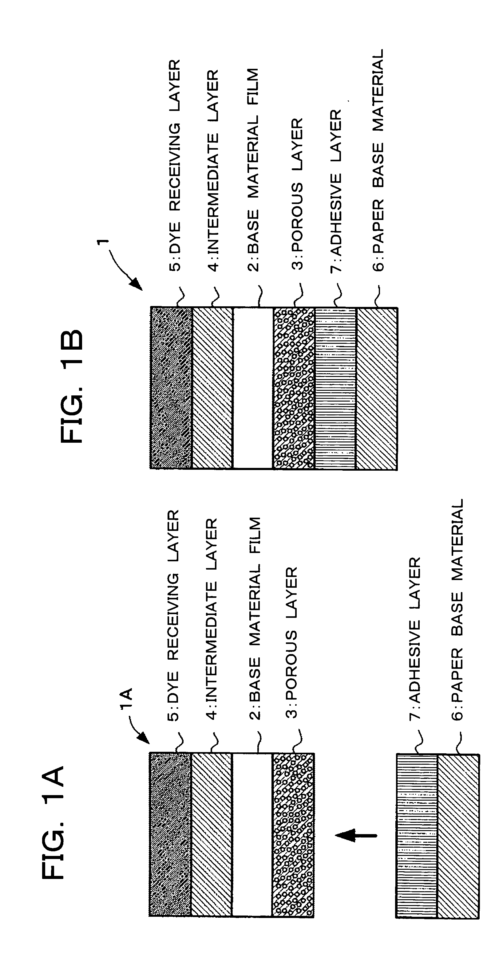
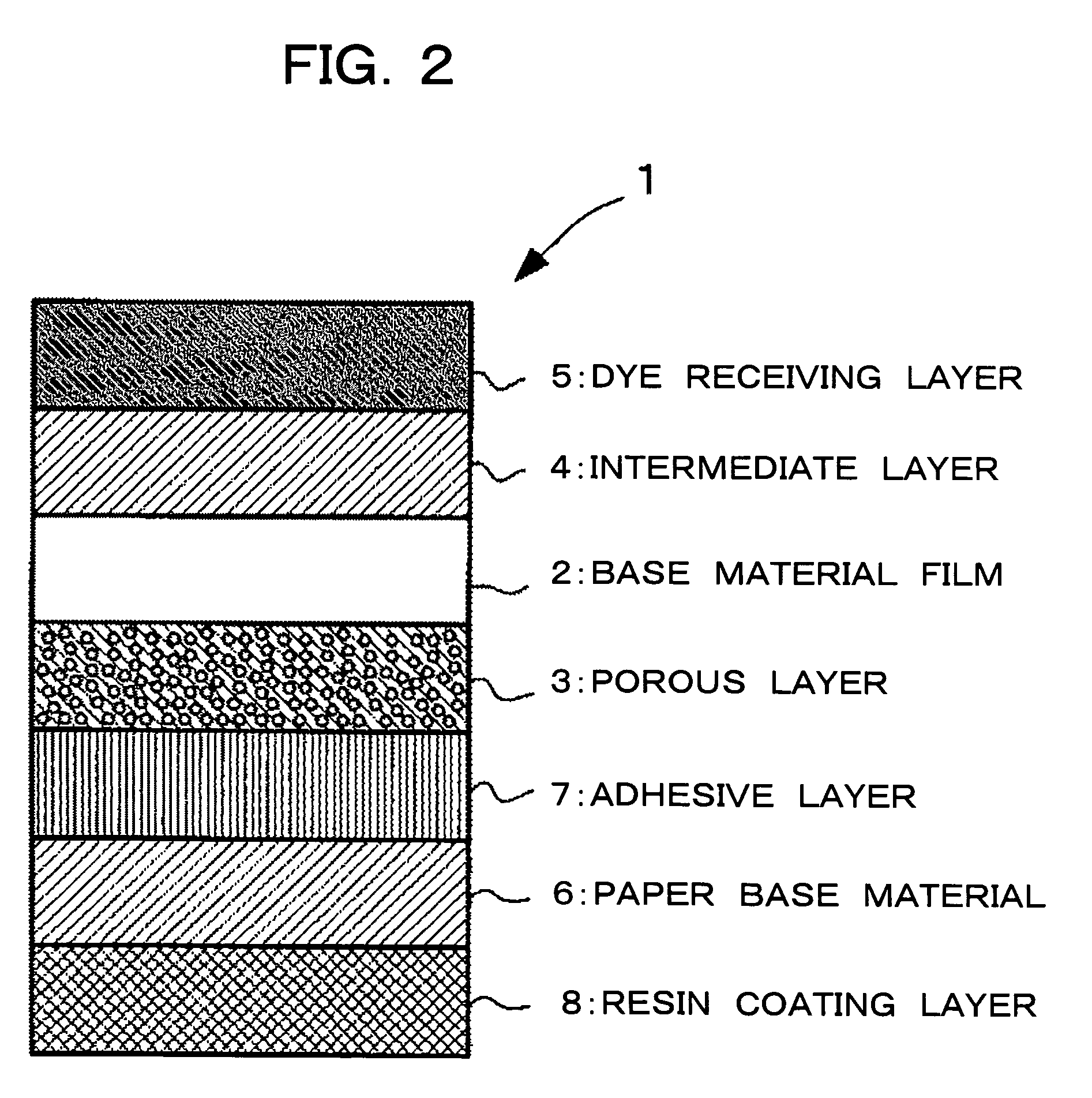
FIG. 1B shows the cross sectional structure of a thermal transfer image receiving sheet 1 according to an embodiment of the present invention, and FIG. 1A shows the state of the halfway of the formation of the thermal transfer image receiving sheet 1. In FIGS. 1A and 1B, the layers are described in a constant thickness for the convenience regardless of the actual thicknesses in the thermal transfer image receiving sheet. As shown in FIG. 1A, the thermal transfer image receiving sheet 1 is manufactured by forming a porous layer 3 on the lower surface side of a base material film 2 and an intermediate layer 4 and a dye receiving layer 5 on the upper surface side successively so as to provide a laminated member 1A, and attaching a paper base material 6 on the lower surface of the porous layer 3 of the laminated member 1A via an adhesive layer 7.

It is preferable that the base material film 2 does not absorb the moisture content or barely absorb the same at the time of coating the poro...

second embodiment

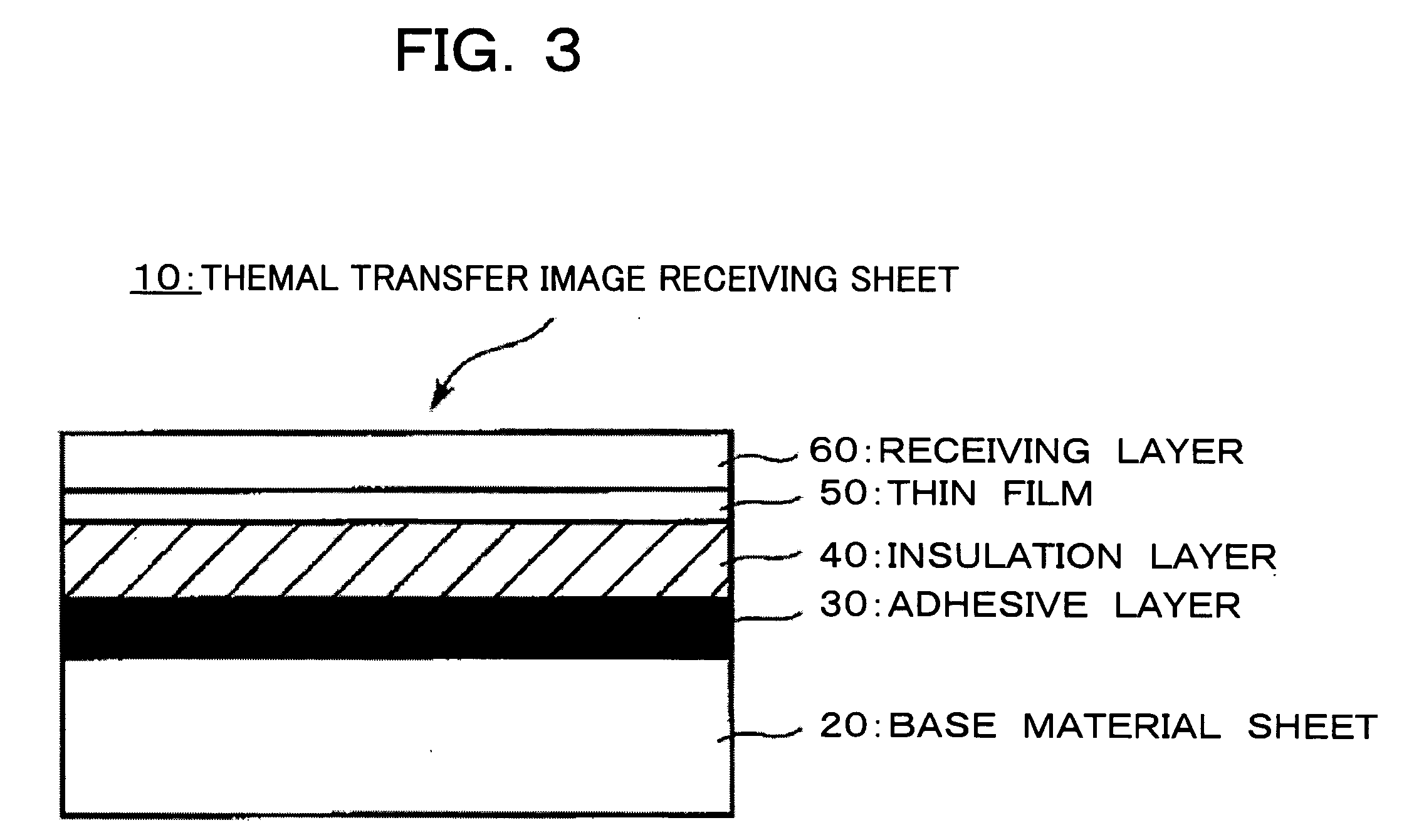
Hereinafter, the second embodiment of the present invention will be explained. FIG. 3 is a schematic cross sectional view showing an example of a thermal transfer image receiving sheet of a second embodiment of the present invention.

It is a thermal transfer image receiving sheet 10 having an adhesive layer 30, an insulation layer 40, a thin film 50 and a receiving layer 60 laminated successively on a base material sheet 20. The insulation layer 40 is formed by providing a resin layer containing a foaming agent or a thermally expansible micro capsule to the thin film 50, and foaming or expanding the resin layer by contacting the resin layer with an extruded resin at the time of EC laminating the resin layer side of the thin film 50 and the base material sheet 20. The layer formed by the extruded resin to be EC laminated is the adhesive layer 3.

The thermal transfer image receiving sheet of the present invention is not limited to the embodiment shown in FIG. 3, and a layer can be ...

example 1-1

By coating an intermediate layer and a dye receiving layer of the below-mentioned compositions on one side surface of a polyester film (produced by Toray Industries, Inc., product name: LUMIRROR) having a thickness of 6 μm as the base material film each in a dry coating amount of 2.0 g / m2 and 4.0 g / m2 by the gravure coating method, and drying them, the intermediate layer and the dye receiving layer of the ther0mal transfer image receiving sheet of Example 1-1 was formed.

(1) Intermediate layerPolyester resin (VYLON 200, produced 10 parts by weightby Toyobo Co., Ltd.)Titanium oxide (TCA-888, produced by 20 parts by weightTohkem Products Co., Ltd.)Methyl ethyl ketone / toluene = 1 / 1120 parts by weight

(2) Dye receiving layerVinyl chloride.vinyl acetate copolymer100 parts by(Denki Kagaku KogyoKabushiki Kaisha, #1000 A)weightAmino modified silicone 5 parts by weight(Shin-Etsu Chemical Co., Ltd.,X22-3050C)Epoxy modified silicone 5 parts by weight(Shin-Etsu Chemical Co., Ltd.,X22-3000E)Met...


PUM

PropertyMeasurementUnit
thicknessaaaaaaaaaa
thicknessaaaaaaaaaa
thicknessaaaaaaaaaa

Abstract

The present invention provides a thermal transfer image receiving sheet having a good productivity, capable of inexpensively obtaining an image with high density and high resolution. A dye receiving layer is provided on one surface side of a base material film, and a porous layer with hollow particles bonded by a binder resin provided on the other surface side, respectively. The porous layer is attached with a base material via an adhesive layer.

Description

BACKGROUND OF THE INVENTION 1. Field of the Invention The present invention relates to a thermal transfer image receiving sheet to be used in a state superimposed with a thermal transfer sheet. 2. Description of the Related Art As a method for forming an image utilizing the thermal transfer, a method for forming a full color image with a thermal transfer sheet having a sublimation dye as a recording material supported by the surface of a base material sheet made of a paper, a plastic film or the like and a thermal transfer image receiving sheet provided with a receiving layer of a sublimation dye on the surface of a paper or a plastic sheet superimposed, is known. According to the method, since the sublimation dye is used as the color material, the density gradation can be adjusted freely so that the original full color image can be expressed on the image receiving sheet. Since the image formed by the dye is extremely vivid and has the excellent transparency, the excellent repro...

Claims


Application Information

Patent Timeline
Patent Type & Authority Applications(United States)
IPC IPC(8): B41M5/40B41M5/42B41M5/44
CPCB41M5/44B41M5/42
Inventor OMATA, TAKENORISUZUKI, TAROOSHIMA, KATSUYUKI
Owner DAI NIPPON PRINTING CO LTD
Why Eureka
Try Eureka