Hydrodynamic bearing device

a technology of bearing device and hydraulic pressure, which is applied in the direction of sliding contact bearing, record information storage, instruments, etc., can solve the problems of reducing the quantity of lubricating fluid as a whole, deteriorating lubricating fluid, and becoming insufficient, so as to improve the bearing loss torque, simplify the structure, and avoid the effect of increasing the bearing loss torqu

Inactive Publication Date: 2005-05-10
SANKYO SEIKI MFG CO LTD +1
View PDF16 Cites 25 Cited by
  • Summary
  • Abstract
  • Description
  • Claims
  • Application Information

AI Technical Summary

Benefits of technology

[0008]It is, therefore, an object of the present invention to provide a dynamic pressure bearing apparatus capable of excellently preventing a lubricating fluid from leaking to the outside with a simple structure.
[0011]According to the dynamic pressure bearing apparatus of the present invention having such a structure, the lubricating fluid in a space formed by the bearing gap (which will be simply referred to as a bearing gap in this specification) is constantly subject to pressure application toward the closed side of the bearing gap by the inward pressure application force giving action of the fluid pressure applying means, and the gas-liquid interface of the lubricating fluid in the bearing gap is maintained on the bearing inner side so as to be pushed toward the inner side by the inward pressure application force giving action, thereby excellently preventing the lubricating fluid from leaking from the seal portion provided on the opened side of the bearing gap.
[0012]On the other hand, in the thrust dynamic pressure bearing portion, when members which are in contact with each other while rotation is at a halt relatively float in the thrust direction and are separated from each other as rotation starts, the lubricating fluid flows into a part which has been in the contact state, namely, a space between the end portion of the shaft member and the counter plate concurrently with the floatation action. At this moment, the lubricating fluid whose quantity is required for inflow moves, the shortfall moves from the opened side to the closed side of the bearing gap, and the gas-liquid interface in the seal portion also moves to the bearing gap side in accordance with this movement. At this moment, since a quantity of the lubricating fluid to be filled is set to a quantity enough to fill the fluid pressure applying means even if movement of the gas-liquid interface toward the bearing gap side occurs, which is produced when the shaft member and the thrust plate relatively float in the thrust direction, the gas-liquid interface of the lubricating fluid which has moved to the bearing gap side does not reach the fluid pressure applying means which gives the inward pressure application force which is directed from the opened side to the closed side of the bearing gap, for example, the radial dynamic pressure generating grooves or the thrust dynamic pressure generating grooves having a shape which generates the unbalanced dynamic pressure that the dynamic pressure having an inward vector component and the dynamic pressure having an outward vector component are simultaneously generated and the dynamic pressure having the inward vector component surpasses, and the inward pressure application force giving action is not reduced. As a result, the above-described effect of preventing the lubricating fluid from leaking to the outside can be stably obtained. Additionally, the present invention can excellently avoid external leak of the lubricating fluid with the simple structure, prolong the duration of life of the dynamic pressure bearing apparatus and increase the reliability. In particular, when the fluid pressure applying means is constituted by utilizing the radial dynamic pressure generating grooves or the thrust dynamic pressure generating grooves, there is no restriction in space, and the simpler structure can be realized without requiring additional groove machining.
[0014]Moreover, in the dynamic pressure bearing apparatus according to the present invention, an angle formed by opposed surfaces of the shaft member and the bearing member constituting the capillary seal portion is designed so as to be large at the boundary with the bearing gap and become continuously or discontinuously smaller as distanced away from the boundary, and the lubricating fluid is filled so that the gas liquid interface of the lubricating fluid is at a position where the angle is small in the capillary seal portion before the shaft member and the thrust plate relatively float. In this case, a capacity of the seal portion is increased, and the duration of life of the bearing is prolonged. Also, a positional movement quantity of the gas-liquid interface of the lubricating fluid is restricted to a small range, and hence it is particularly effective when the entire apparatus is reduced in thickness.
[0016]When a pressure is applied to the lubricating fluid in the bearing gap toward the closed side based on provision of the inward pressure application force of the fluid pressure applying means, a floatation quantity in the axial direction in the thrust dynamic pressure bearing portion is increased by a quantity corresponding to the pressure application, the bearing gap in the thrust dynamic pressure bearing portion becomes uneven, and an increase in the bearing loss torque can be considered. In the present invention, however, the magnetic suction means for generating a suction force corresponding to provision of the inward pressure application force of the fluid pressure applying means is provided, and the bearing gap in the thrust dynamic pressure bearing portion is evenly maintained by the magnetic suction means. As a result, an increase in the bearing loss torque can be excellently avoided. Further, when the magnetic suction member which generates a suction force corresponding to a floatation force of the thrust bearing portion is provided at a position opposed to the rotor magnet, the magnetic force of the rotor magnet can be utilized, and hence the magnetic suction force can be obtained by only providing the magnetic suction member, thereby simplifying the structure.
[0017]Furthermore, when the bearing gap is used with the opened side thereof facing downward, the effect of preventing the lubricating fluid from leaking to the outside can be stably realized by adopting the magnetic suction member having a suction force larger than a weight of a rotation side member as with the present invention, and the rotation side member can be excellently prevented from coming off in the axial direction.

Problems solved by technology

Therefore, when the lubricating fluid is independently filled in each dynamic pressure bearing portion, a quantity of the lubricating fluid is reduced as a whole, and the lubricating fluid is deteriorated due to oxidation or gelation or becomes insufficient due to evaporation or the like.
As a result, the duration of life of the bearing is shortened, and there occurs a problem that the lubricating fluid is apt to leak due to a change in pressure or a change in temperature.
However, even if the entire area of the bearing gaps is completely filled with the lubricating fluid, air bubbles may be possibly generated at a negative pressure part produced in the bearing portion.
Therefore, there is the risk that the lubricating fluid may be pushed toward the outside of the bearing by the air bubbles and the lubricating fluid may leak to the outside.

Method used


Image

  • Hydrodynamic bearing device
  • Hydrodynamic bearing device
  • Hydrodynamic bearing device

Examples


Embodiment Construction

[0034]Although an embodiment in which the present invention is applied to a hard disk drive (which will be referred to as an HDD hereinafter) will be described hereunder, the entire structure of the HDD will be first explained with reference to the accompanying drawings.

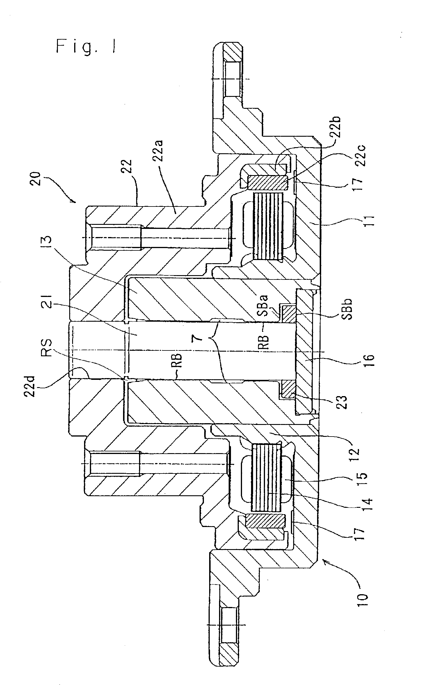
[0035]An HDD spindle motor which is of an axial rotation type shown in FIG. 1 is constituted by a stator unit 10 as a fixing member and a rotor unit 20 as a rotation member assembled to the stator unit 10 from the upper side in the drawing. In these units, the stator unit 10 has a fixed frame 11 which is screwed to a non-illustrated fixing base. This fixed frame 11 is formed of aluminium or an aluminium alloy based metal material in order to reduce the weight. Further, a bearing sleeve 13 as a fixed bearing member formed into a hollow cylindrical shape is joined to an annular bearing holder 12, which is formed so as to be erect at the substantially central part of the fixed frame 11, by press fitting or shrink fittin...


PUM

PropertyMeasurementUnit
radiusaaaaaaaaaa
radiusaaaaaaaaaa
diameteraaaaaaaaaa

Abstract

A bearing has a thrust plate integrated with its shaft and a bearing member surrounds both. A radial pressure bearing portion and separate thrust portion generate pressure on a lubricating fluid in a gap between the shaft and bearing member. One end of the gap is closed while the other is open and has a capillary seal formed with an angle that is large at a boundary but smaller at increasing distance therefrom. The fluids fills the gap so that gas-fluid interface is where the angle is small and causes the thrust plate to float. A pressure mechanism forces the fluid from the open to the closed end and the quantity of fluid is set to fill the mechanism even if the gas-fluid interface moves.

Description

TECHNICAL TERM[0001]A dynamic pressure surface used in this specification means a shaft portion or a bearing surface having dynamic pressure generating grooves provided thereto, and a circumferential surface of a bearing surface or a shaft portion in an area corresponding to the former shaft portion or the bearing surface. Further, a dynamic pressure bearing portion means an area configured by dynamic pressure surfaces and a lubricating fluid filled between the such surfaces, in which a dynamic pressure is generated. Furthermore, a bearing gap means all gaps between a shaft member, a thrust plate and a bearing member which surrounds them irrespective of presence / absence of generation of the dynamic pressure.TECHNICAL FIELD[0002]The present invention relates to a bearing apparatus. More particularly, the present invention relates to a dynamic pressure bearing apparatus which causes a shaft member and a bearing member to float so as to be capable of relative rotation by a dynamic pres...

Claims


Application Information

Patent Timeline
Patent Type & Authority Patents(United States)
IPC IPC(8): F16C33/04F16C33/10F16C33/74F16C33/72G11B33/14G11B19/20F16C17/02
CPCF16C17/02F16C17/107F16C33/107G11B19/2018G11B33/1473F16C33/74F16C2370/12
Inventor GOMYO, MASATOSATO, MASAAKI
Owner SANKYO SEIKI MFG CO LTD
Why Eureka
Try Eureka