Supercharge Your Innovation With Domain-Expert AI Agents!

Control apparatus, image pickup apparatus, control method, and non-transitory computer-readable storage medium for performing focus detection

a control apparatus and focus detection technology, applied in the field of image pickup apparatus, can solve the problem of difficulty in performing focus detection with high accuracy, and achieve the effect of high accuracy

Active Publication Date: 2018-08-28
CANON KK
View PDF12 Cites 1 Cited by
  • Summary
  • Abstract
  • Description
  • Claims
  • Application Information

AI Technical Summary

Benefits of technology

[0008]The present invention provides a control apparatus, an image pickup apparatus, a control method, and a non-transitory computer-readable storage medium which are capable of reducing a difference between a detected in-focus position based on a focus detection signal and a best in-focus position based on an imaging signal to perform focus detection with high accuracy.

Problems solved by technology

However, in the imaging-plane phase difference method, a spatial frequency band of a focus detection signal for the focus detection may be different from a spatial frequency band of an imaging signal for generating a captured image.
In this case, a difference between a detected in-focus position based on the focus detection signal and a best in-focus position based on the imaging signal occurs, and accordingly it is difficult to perform the focus detection with high accuracy.

Method used


Image

  • Control apparatus, image pickup apparatus, control method, and non-transitory computer-readable storage medium for performing focus detection
  • Control apparatus, image pickup apparatus, control method, and non-transitory computer-readable storage medium for performing focus detection
  • Control apparatus, image pickup apparatus, control method, and non-transitory computer-readable storage medium for performing focus detection

Examples


embodiment 1

[Embodiment 1]

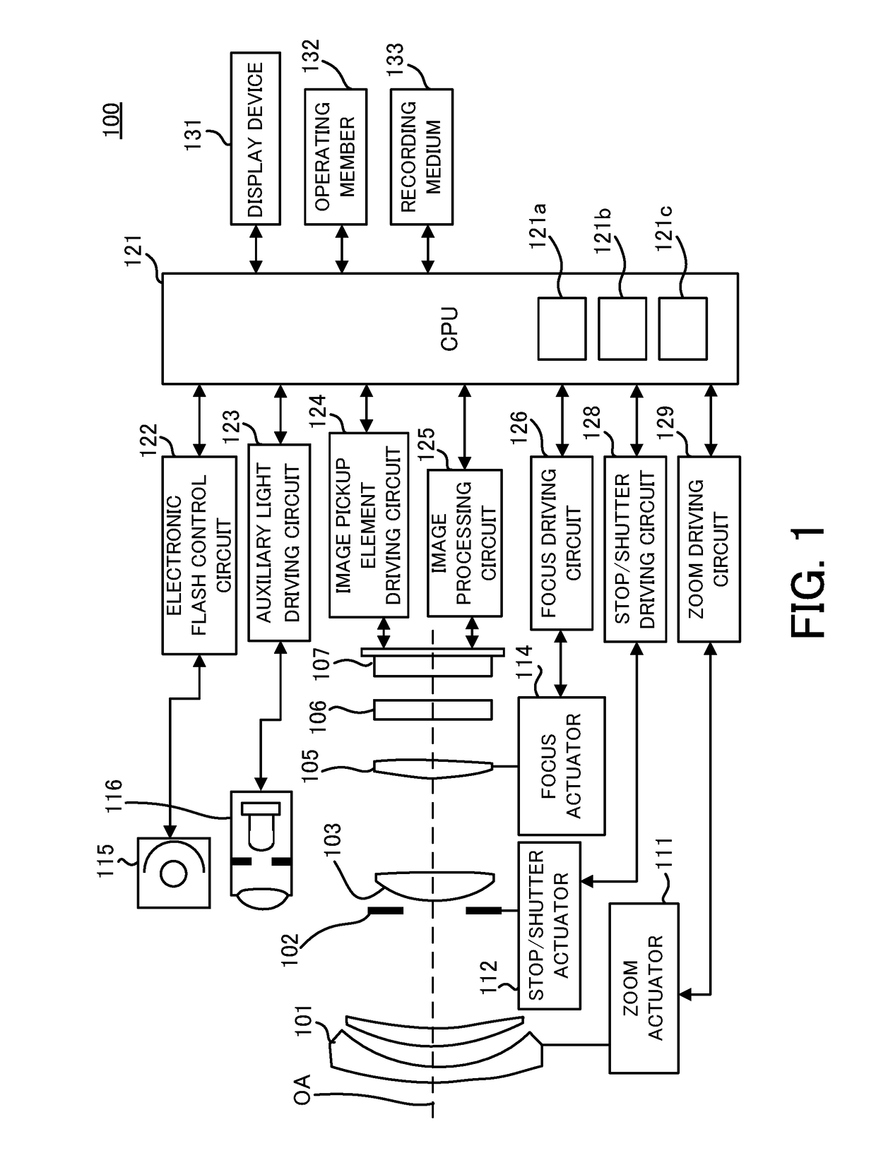
[0033]First of all, referring to FIG. 1, a schematic configuration of an image pickup apparatus in Embodiment 1 of the present invention will be described. FIG. 1 is a block diagram of an image pickup apparatus 100 (camera) in this embodiment. The image pickup apparatus 100 is a digital camera system that includes a camera body and an interchangeable lens (imaging optical system or image pickup optical system) removably attached to the camera body. However, this embodiment is not limited thereto, and can be applied also to an image pickup apparatus including a camera body and a lens which are integrated with each other.

[0034]A first lens unit 101 is disposed at the forefront side (object side) of a plurality of lens units that constitute an imaging lens (imaging optical system), and it is held on a lens barrel so as to be movable back and forth in a direction of an optical axis OA (optical axis direction). A stop / shutter 102 (aperture stop) adjusts its opening diameter...

embodiment 2

[Embodiment 2]

[0114]Next, referring to FIG. 14, second pixel addition processing in Embodiment 2 of the present invention will be described. FIG. 14 is an explanatory diagram of the second pixel addition processing. This embodiment is different only in the second pixel addition processing from Embodiment 1, and accordingly other descriptions are omitted.

[0115]In FIG. 14, the first focus detection signal at j-th in a column direction (pupil division direction) and at i-th in a row direction (direction orthogonal to the pupil division direction) in Bayer array is represented by A (i, j). The first focus detection signal is indicated for each of colors of R, G, and B. The first focus detection signal of R (first color) is represented by RA(i, j)=A (i, j). The first focus detection signal of G (second color) is represented by GA(i,j+1)=A(i,j+1) and GA(i+1,j)=A(i+1,j). The first focus detection signal of B (third color) is represented by BA(i+1,j+1)=A(i+1,j+1). Similarly, the second focu...

embodiment 3

[Embodiment 3]

[0121]Next, referring to FIG. 15 and FIGS. 16A and 16B, an image pickup apparatus in Embodiment 3 of the present invention will be described. This embodiment is different from Embodiment 1 in the pixel array of the image pickup element 107. Other configurations in this embodiment are the same as those in Embodiment 1, and accordingly descriptions thereof are omitted.

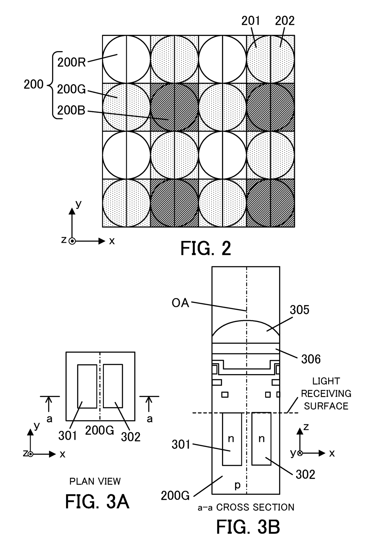
[0122]FIG. 15 is a diagram of illustrating the pixel array of the image pickup element 107 in this embodiment. FIGS. 16A and 16B are diagrams of illustrating the pixel structure of the image pickup element 107, and FIGS. 16A and 16B illustrate a plan view of a pixel 200G of the image pickup element 107 (view in a +z direction) and a cross-sectional view along a line a-a in FIG. 16A (view in a -y direction), respectively.

[0123]FIG. 15 illustrates the pixel array (array of imaging pixels) of the image pickup element 107 (two-dimensional CMOS sensor) in a range of 4 columns×4 rows. In this embodiment, each of ...


PUM


Abstract

A control apparatus (121) includes a generation unit (121a) for generating first and second focus detection signals based on a plurality of types of color signals from first and second pixel groups that receive light beams passing through partial pupil regions different from each other, and a calculation unit (121b) for calculating a defocus amount by a phase difference detection method by using the first and second focus detection signals, and the generation unit combines the color signals with respect to the first pixel group so that centroids of the color signals in a pupil division direction coincide with each other to generate the first focus detection signal, and combines the color signals with respect to the second pixel group so that centroids of the color signals in the pupil division direction coincide with each other to generate the second focus detection signal.

Description

BACKGROUND OF THE INVENTION[0001]Field of the Invention[0002]The present invention relates to an image pickup apparatus which performs focus detection by a phase difference detection method.[0003]Description of the Related Art[0004]Conventional image pickup apparatuses which perform focus detection of a phase difference detection method (imaging-plane phase difference method) by using focus detection signals from an image pickup element are known.[0005]U.S. Pat. No. 4,410,804 discloses an image pickup apparatus using a two-dimensional image pickup element in which a single microlens and a plurality of divided photoelectric conversion portions are formed for each pixel. The divided photoelectric conversion portions receive light beams passing through different partial pupil regions of an exit pupil of an imaging lens via the single microlens for dividing the pupil. An image shift amount can be calculated based on each of focus detection signals that are received by the divided photoe...

Claims


Application Information

Patent Timeline
Patent Type & Authority Patents(United States)
IPC IPC(8): H04N5/232H04N5/369H04N5/357H04N5/225
CPCH04N5/23212H04N5/2256H04N5/3696H04N5/23296H04N5/3572H04N5/23293H04N23/56H04N23/672H04N25/704H04N25/134H04N23/69
Inventor FUKUDA, KOICHI
Owner CANON KK
Features
  • R&D
  • Intellectual Property
  • Life Sciences
  • Materials
  • Tech Scout
  • Unparalleled Data Quality
  • Higher Quality Content
  • 60% Fewer Hallucinations
Learn More