Rotary ground auger base and feeder stand

Active Publication Date: 2018-09-04
DECOY STAKE SOLUTIONS LLC
View PDF28 Cites 8 Cited by
  • Summary
  • Abstract
  • Description
  • Claims
  • Application Information

AI Technical Summary

Benefits of technology

[0014]It is an object of this invention to provide a rotary ground auger base and stand with a helical coil at one end and a crank handle which can be used to thread the coil into the ground, thus forming a rigid connection with the ground and providing secure support for a feeder.

Problems solved by technology

Some feeding stands have one or more spikes which are hammered into the ground with a hammer, rock, limb, or other tool; however, problems occur due to the inability to penetrate the earth, or the stand becoming loose due to wind and wear so that it falls over or the decoy spins around in an undesirable position.

Method used


Image

  • Rotary ground auger base and feeder stand
  • Rotary ground auger base and feeder stand
  • Rotary ground auger base and feeder stand

Examples


Embodiment Construction

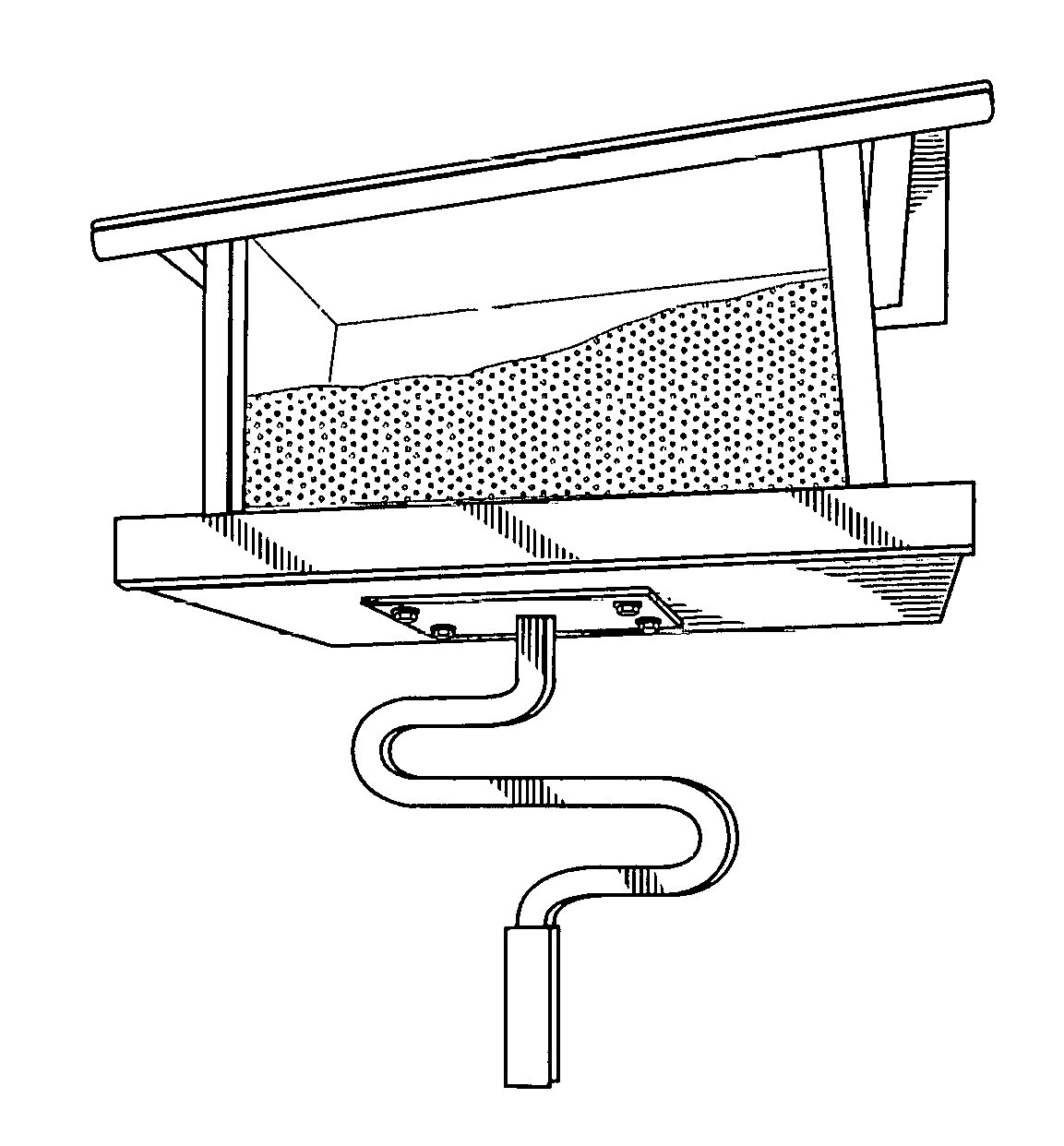
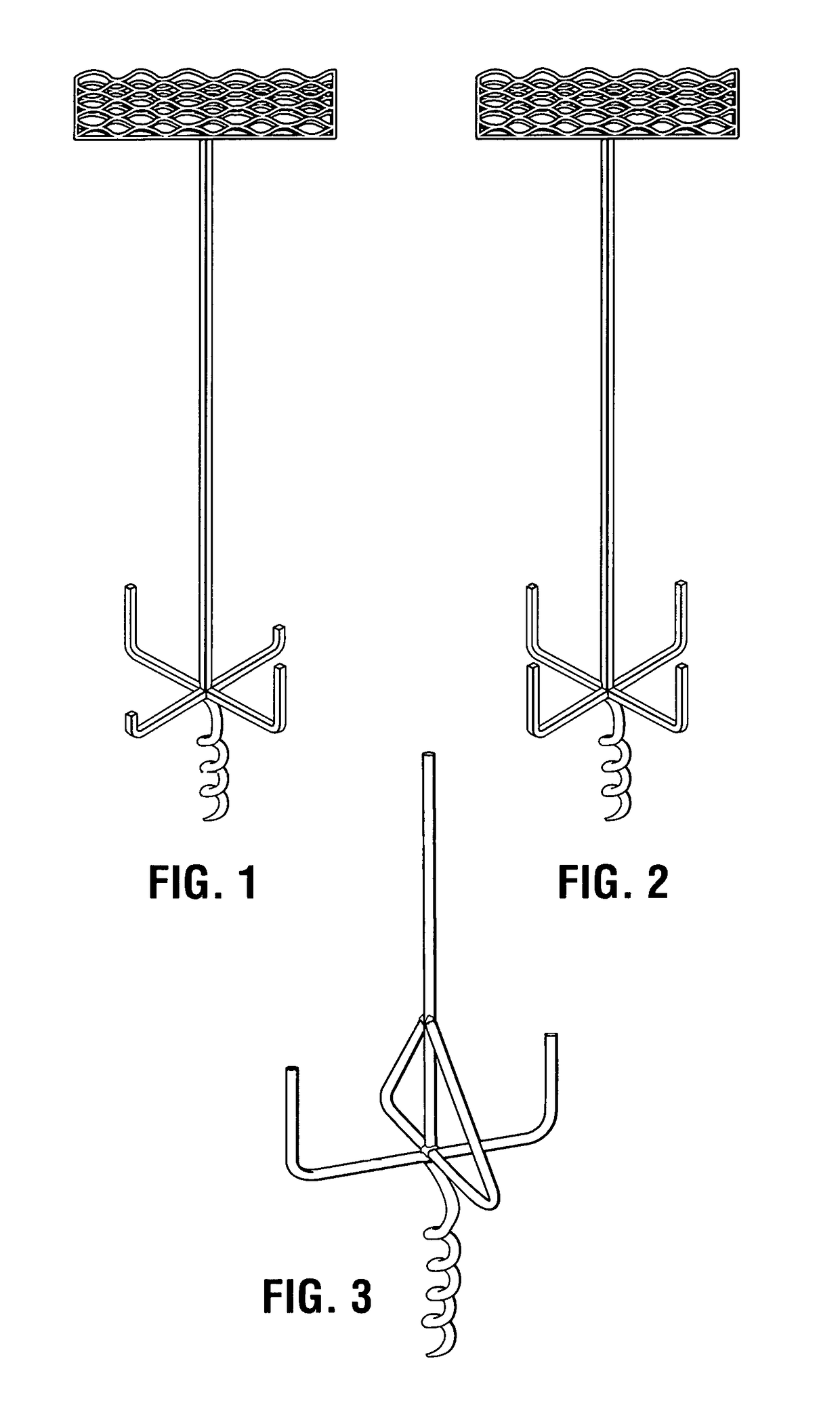
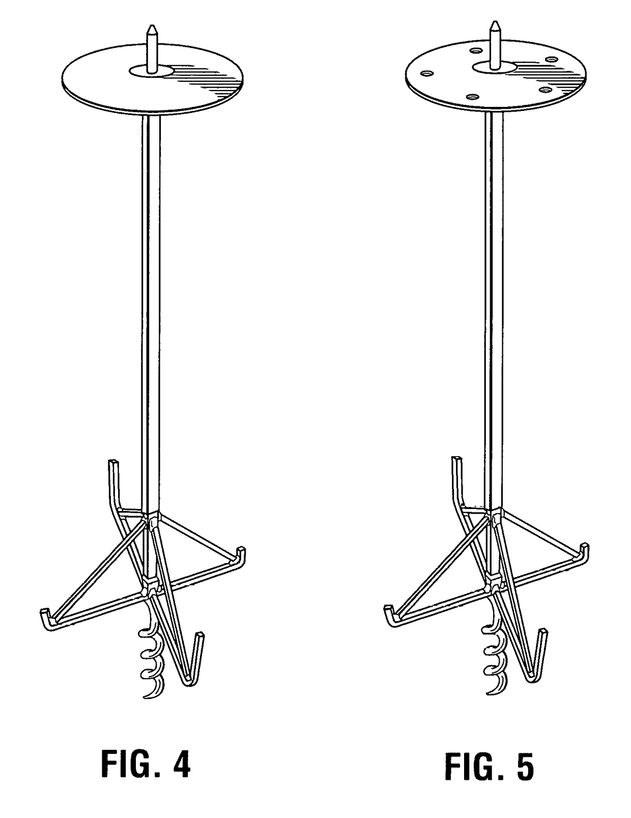
[0034]In accordance with the present invention, there is provided a rotary ground auger base and stand 10 for holding a feeder or camera in a raised position above the ground for the intended use.

[0035]The rotary auger support stand includes a bottom section extending from a bottom distal end of the medial section, the bottom section comprising a helical spiral coil extending downward therefrom a selected distance including a tapered point for penetration into the ground. A medial section extends upward from the bottom section having a generally vertical rod. A handle section extending from the medial section comprising a curved rod forming at least one “S” shaped loop comprising a first horizontal segment extending outwardly from the medial section at a generally 90 degree angle a selected first length and having a proximate end portion curving upward forming a first 180 degree curved loop extending upward and over the first horizontal segment and past the medical section a selecte...


PUM


Abstract

A feeder stand including a rotary ground auger and base holds a feeder above the ground. An upright elongated rod defines a stand supported by an auger having helical coils removably screwed into the ground. A platform such as a round disc, or wire mesh platform is supported on the top distal end of the rod. At least two opposing legs extend perpendicular to the vertical elongated rod and auger forming a base. The distal end of selected opposing legs are bent or angled upward perpendicular from the ground forming handles for rotating the auger into the ground. The portion of the legs extending outward normal to the elongated support pole provides a base bearing against the ground for increased lateral support.

Description

CROSS REFERENCES TO RELATED APPLICATIONS[0001]This application claims priority from U.S. Provisional Application Ser. No. 62 / 389,738 filed on Mar. 9, 2016 and is Continuation-In-Part of U.S. application Ser. No. 14 / 999,090 filed on Mar. 29, 2016 which is a Continuation-In-Part of U.S. application Ser. No. 14 / 999,498 filed on Feb. 25, 2016 all of which are incorporated herein in their entirety.TECHNICAL FIELD[0002]The present invention relates to the field of removable and portable feeder stands.BACKGROUND OF THE INVENTION[0003]Birds, Duck, turkey, geese and other water fowl hunters and bird watchers use feeders for attracting the fowl. Often times, feeders are supported on a pole, anchored, or supported by a stake which holds the feeder in a preferred position which is likely to attract feeding fowl. Some feeding stands have one or more spikes which are hammered into the ground with a hammer, rock, limb, or other tool; however, problems occur due to the inability to penetrate the ea...

Claims


Application Information

Patent Timeline
Patent Type & Authority Patents(United States)
IPC IPC(8): A01K1/04A01M31/00A01K5/015E02D5/80F41B5/14A45F3/44A01K39/01
CPCA45F3/44A01K5/015A01K39/0106F41B5/1453A01M31/008E02D5/801A01M31/00
Inventor BROOKS, KEVIN
Owner DECOY STAKE SOLUTIONS LLC
Why Eureka
Try Eureka