Hybrid brake control

a technology of hybrid brakes and control devices, applied in the field of vehicles, can solve the problems of time-consuming switching of braking force, different desired braking, etc., and achieve the effect of improving fuel consumption and reducing braking distan

Active Publication Date: 2018-09-04
TOYOTA JIDOSHA KK
View PDF17 Cites 4 Cited by
  • Summary
  • Abstract
  • Description
  • Claims
  • Application Information

AI Technical Summary

Benefits of technology

[0009]An aspect of the invention provides a vehicle. The vehicle includes a brake operation detector, a friction brake, a regenerative brake, and an electronic control unit (ECU). The brake operation detector is configured to detect a driver's brake operation amount. The ECU is configured to: (a) control a total braking force that is generated in the vehicle by controlling the friction brake and the regenerative brake; (b) execute first brake control for controlling a braking force of the vehicle on the basis of the brake operation amount; (c) determine based on the brake operation amount whether the driver's brake operation is being carried out; (d) when the ECU determines that the driver's brake operation is not being carried out, execute second brake control for automatically controlling the braking force of the vehicle in response to a condition of the vehicle, other than the brake operation amount; and (e) when the second brake control is executed, reduce a proportion of a braking force of the regenerative brake within the total braking force as compared to when the first brake control is executed.
[0010]When the proportion of the braking force of the regenerative brake is high, it is advantageous in reducing a fuel consumption. On the other hand, when the proportion of the braking force of the regenerative brake is low, because a replacement amount in process of replacing the braking force of the regenerative brake with the braking force of the friction brake becomes small, controllability is high, and it is possible to reduce the braking distance. According to the above aspect, the amount of regeneration is ensured by a large amount by placing importance on fuel consumption during first brake control (during ordinary brake control); however, it is possible to reduce the braking distance by placing importance on controllability by reducing the amount of regeneration during second brake control (during automatic brake control).
[0012]According to the above aspect, the proportion of the braking force of the regenerative brake is set to zero from the beginning when stop control is executed, so it is not required to switch the braking force from the regenerative brake to the friction brake at the time of a stop, and it is possible to reduce the braking distance. On the other hand, it is not required to place importance on the braking distance when deceleration control is executed, so it is possible to improve the fuel consumption by also carrying out regeneration.
[0014]According to the above aspect, the first ECU executes brake control without waiting for a response from the second ECU during second brake control (automatic brake control), so it is possible to reduce a control time corresponding to a delay in communication resulting from coordinated control with the regenerative brake during second brake control.
[0016]According to the invention, it is possible to reduce the braking distance during automatic brake control while improving the fuel consumption by using the regenerative brake as much as possible.

Problems solved by technology

Therefore, when regenerative braking is activated at a large proportion for the purpose of improvement in fuel consumption, there is an inconvenience that switching of braking force takes time.
Therefore, desired braking is different between braking caused by driver's operation and braking caused by the system; however, the brake system described in Japanese Patent No. 3438242 does not take such a point into consideration.

Method used


Image

  • Hybrid brake control
  • Hybrid brake control
  • Hybrid brake control

Examples


Embodiment Construction

[0023]Hereinafter, an embodiment of the invention will be described in detail with reference to the accompanying drawings. Like reference numerals denote the same or corresponding portions in the drawings, and the description thereof will not be repeated.

Description of Outline of Vehicle Including Brake System

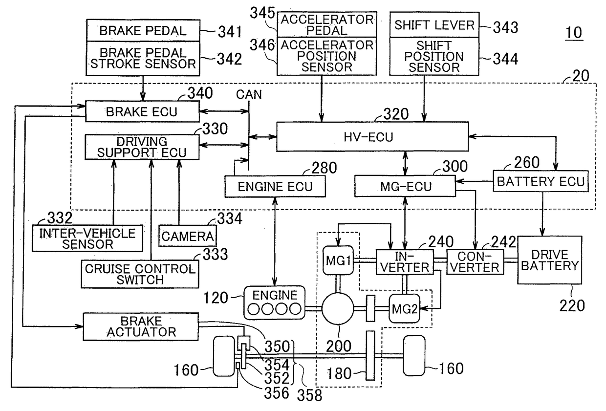
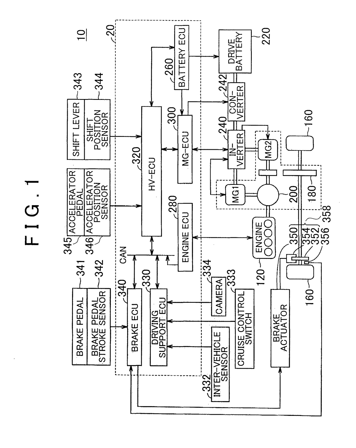
[0024]FIG. 1 is a block diagram that shows the major configuration of a vehicle according to the embodiment. As shown in FIG. 1, the vehicle 10 according to the present embodiment includes a brake pedal 341 (brake operating unit), a friction brake 358, a regenerative brake and a control unit 20. The brake pedal 341 is operated by a driver. The regenerative brake uses a motor generator MG2. The control unit 20 controls the total braking force that is generated in the vehicle 10 by using the friction brake 358 and the regenerative brake. The control unit 20 executes ordinary brake control or automatic brake control. In the ordinary brake control, the vehicle is braked on the basi...


PUM


Abstract

A vehicle includes a friction brake, a regenerative brake, and an ECU. The ECU is configured to: (a) control a total braking force that is generated in the vehicle; (b) execute first brake control for controlling a braking force of the vehicle on the basis of the brake operation amount; (c) determine based on the brake operation amount whether the driver's brake operation is being carried out; (d) when the ECU determines that the driver's brake operation is not being carried out, execute second brake control for automatically controlling the braking force of the vehicle in response to a condition of the vehicle, other than the brake operation amount; and (e) when the second brake control is executed, reduce a proportion of a braking force of the regenerative brake within the total braking force as compared to when the first brake control is executed.

Description

CROSS-REFERENCE TO RELATED APPLICATIONS[0001]This is a national phase application based on the PCT International Patent Application No. PCT / IB2015 / 000014 filed Jan. 12, 2015, claiming priority to Japanese Patent Application No. 2014-017247 filed Jan. 31, 2014, the entire contents of both of which are incorporated herein by reference.BACKGROUND OF THE INVENTION[0002]1. Field of the Invention[0003]The invention relates to a vehicle and, more particularly, to a vehicle including a regenerative brake and a friction brake.[0004]2. Description of Related Art[0005]Japanese Patent No. 3438242 describes an electric vehicle. The electric vehicle includes a brake system that improves fuel consumption by converting energy during deceleration of the vehicle to electric energy. When an anti-lock brake system is activated while the vehicle is being decelerated by using regenerative braking and friction braking through driver's operation of a brake pedal, the brake system reduces the proportion of ...

Claims


Application Information

Patent Timeline
Patent Type & Authority Patents(United States)
IPC IPC(8): B60L3/00B60T1/10B60T7/04B60T7/12B60L15/20B60W30/18B60W20/14B60L7/14B60L7/26B60L11/12B60L11/14B60L11/18B60T8/176B60L3/10B60T7/22B60L50/15B60L50/16
CPCB60L3/0015B60L3/108B60L7/14B60L7/26B60L11/123B60L11/14B60L11/1861B60L15/2009B60T1/10B60T7/042B60T7/12B60T7/22B60T8/176B60W20/14B60W30/18127B60L3/102Y02T10/7275B60L2210/10B60L2210/40B60L2240/12B60L2240/421B60L2240/423B60L2240/441B60L2240/443B60L2240/445B60L2240/461B60L2240/527B60L2240/545B60L2240/547B60L2240/549B60L2240/80B60L2250/24B60L2250/26B60T2201/022B60T2270/604Y02T10/6217Y02T10/645Y02T10/7005Y02T10/705Y02T10/7044Y02T10/7077Y02T10/7216Y02T10/7241B60T8/58B60K6/445B60L50/16B60L50/61B60L58/12B60W10/08B60W10/184B60W2540/12Y02T10/62Y02T10/64Y02T10/70Y02T10/7072Y02T10/72B60K6/48
Inventor KATSUTA, HIROSHI
Owner TOYOTA JIDOSHA KK
Why Eureka
Try Eureka