Eureka AIR delivers breakthrough ideas for toughest innovation challenges, trusted by R&D personnel around the world.

Systems and methods of tracking rotor blades

a technology of rotor blades and tracking systems, applied in the direction of optical radiation measurement, instruments, transportation and packaging, etc., can solve the problems of system failure, poor lighting, and difficulty in achieving accurate measurements in changing light conditions

Active Publication Date: 2018-09-04
TECH FOR ENERGY CORP
View PDF41 Cites 1 Cited by
  • Summary
  • Abstract
  • Description
  • Claims
  • Application Information

AI Technical Summary

Benefits of technology

[0007]Example embodiments of the present general inventive concept provide improved systems and methods of detecting and tracking rotary blades to compensate for changed lighting conditions and blade characteristics.
[0008]Example embodiments of the present general inventive concept also provide improved systems and methods of detecting and tracking rotary blades to increase the accuracy of rotor blade position and timing measurements during typical aircraft operating conditions. Some embodiments enable the person maintaining the aircraft to make suitable adjustments to improve the rotor operations.
[0025]The system can include adjustable gain electronics to enhance signal levels.
[0027]The processor can also include a low pass filter to remove noise from the output of the sensors and remove noise from the once per revolution signal.

Problems solved by technology

One of the challenges of known techniques is that the measurement relies on light level contrasts between the blade and dynamic background light conditions, making it difficult to achieve accurate measurements during changing light conditions, for example during different times of day, various sun / cloud conditions, etc.
Such systems can struggle in poor lighting conditions where there is little contrast between the blade and the sky such as a dark cloudy day and may not be able to detect the blade pass event.
Moreover, in situations where the sun has a direct path into the optics system, the light can either saturate the detectors or create false events, corrupting the timing measurements.
The difficulties can be exacerbated by differing light deflection and absorption characteristics attributable to different sets of rotor blades, for example due to age of the blades, materials, color schemes, blade coatings, and the like.

Method used


Image

  • Systems and methods of tracking rotor blades
  • Systems and methods of tracking rotor blades
  • Systems and methods of tracking rotor blades

Examples


Embodiment Construction

[0053]Reference will now be made to the example embodiments of the present general inventive concept, examples of which are illustrated in the accompanying drawings and illustrations. The example embodiments are described herein in order to explain the present general inventive concept by referring to the figures.

[0054]Although example embodiments of the present general inventive concept will be particularly described as being applied to helicopter blades, it will be appreciated that the present general inventive concept can be applied to a variety of other rotor-based systems, for example propellers, fans, windmills, or other rotating machinery, without departing from the scope and spirit of the present general inventive concept.

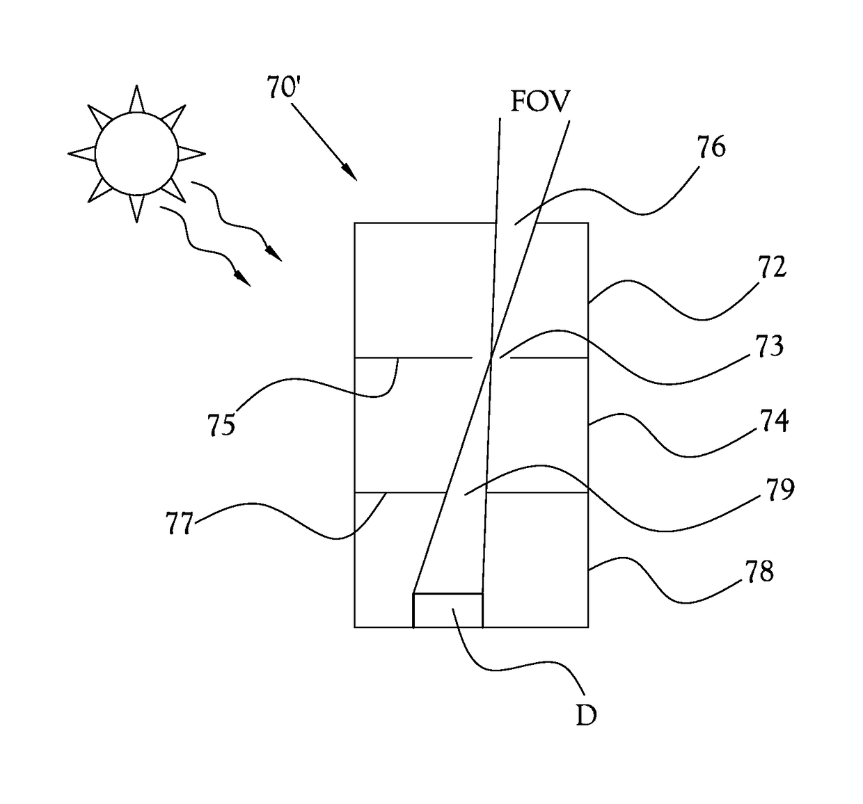
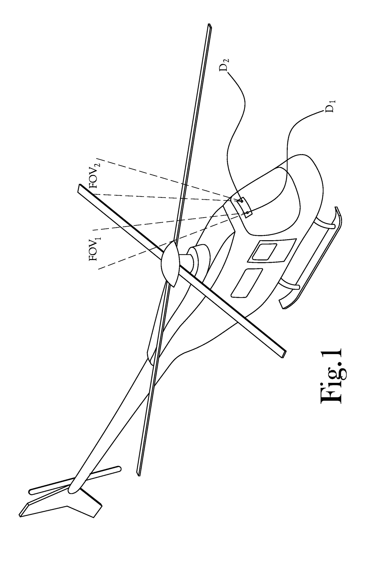
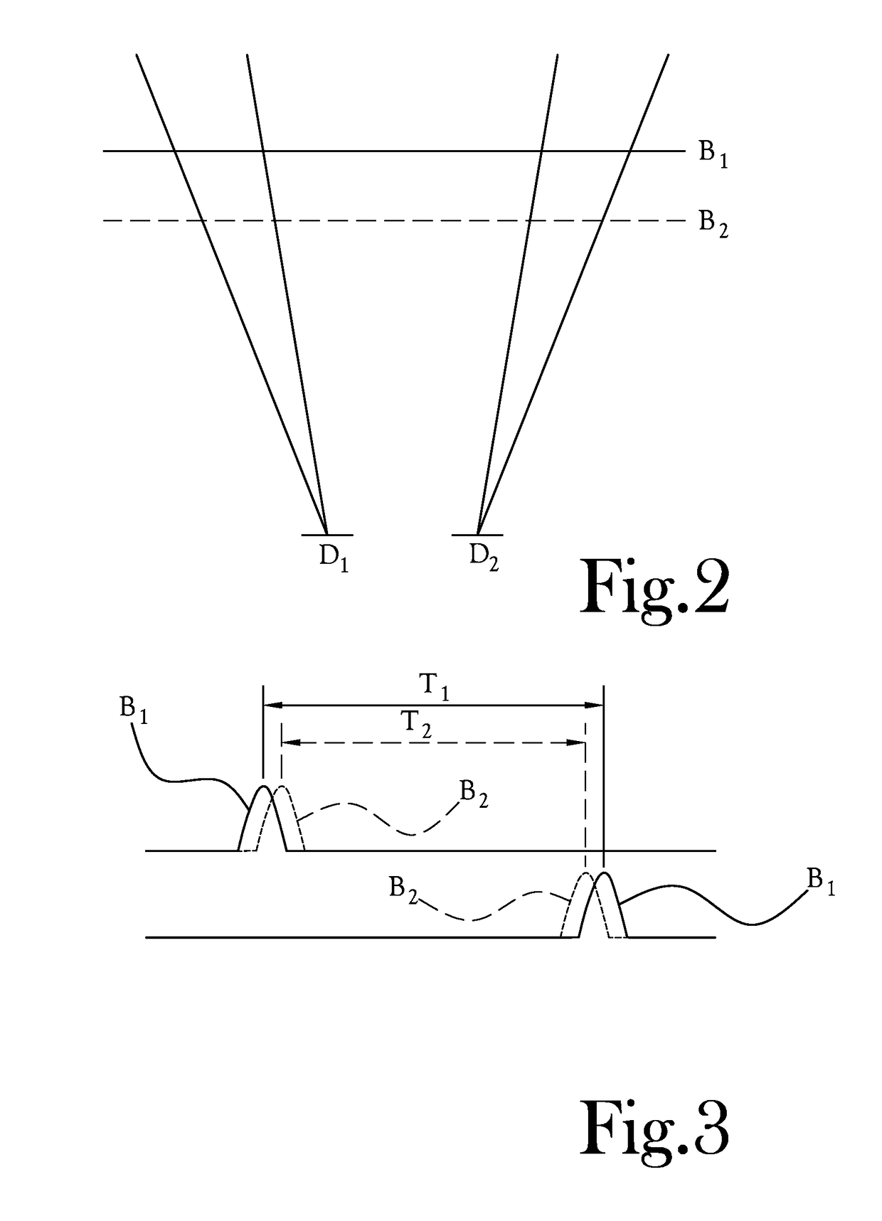
[0055]Referring to FIG. 1, example embodiments of the present general inventive concept can be implemented in connection with a helicopter having a detector system creating one or more divergent fields of view to measure the times at which a helicopter roto...


PUM


Abstract

A blade tracking system including a detector having one or more sensors to detect radiation from at least one field of view of the detector, the one or more sensors generating signals based on changes in incident radiation to the one or more sensors as a rotor blade passes the field of view, and a processor to determine a pass time for the rotor blade to pass through the at least one field of view based on the generated signals.

Description

CROSS-REFERENCE TO RELATED APPLICATIONS[0001]Not ApplicableFIELD OF INVENTIVE CONCEPT[0002]The present inventive concept relates generally to systems and methods of tracking moving objects, and more particularly relates to detecting the position and timing of aircraft rotor blades during operation.BACKGROUND[0003]It is desirable to track the position and timing of aircraft rotor blades in order to maintain, adjust, and improve rotor blade operations. For example, knowing the position of helicopter blades permits the person maintaining the aircraft to make suitable adjustments to improve the rotor operations.[0004]Known techniques for detecting the position and timing of helicopter rotor blades include, for example, the use of optical systems to create an image of a blade tip onto a sensor so that the moving blade will generate a sensor output that can be related to the blade position, and the use of two light sensors to measure the time it takes for a blade to pass between two diver...

Claims


Application Information

Patent Timeline
Patent Type & Authority Patents(United States)
IPC IPC(8): B64C27/00G01J1/02G01J1/06G02B27/30
CPCB64C27/008G01J1/0214G01J1/0266G01J1/0295G01J1/06G02B27/30G01J1/0271G01J2001/061
Inventor SIMPKINS, WILLIAMWILSON, JOHNDORRIS, DAVID
Owner TECH FOR ENERGY CORP
Why Eureka
Eureka Blog
Learn More