
Portable charging case module

a charging case and module technology, applied in the field of portable terminals, can solve the problems of mobile phone charger size, mobile phone charger power being discharged faster than that of the battery of the conventional mobile phone, and achieve the effect of improving the convenience of use of the portable terminal

Inactive Publication Date: 2018-09-04
KOREA ELECTRONICS TECH INST
View PDF9 Cites 3 Cited by
  • Summary
  • Abstract
  • Description
  • Claims
  • Application Information

AI Technical Summary

Benefits of technology

The patent aims to provide a portable charging case that allows for easy attachment and detachment of a case and auxiliary battery part. This allows for easy use of the portable terminal as the battery can be charged when needed. Additionally, the patent aims to provide a modular design that allows for replacement of certain parts when failure or damage occurs. These technical effects improve the convenience and practicality of using portable charging cases.

Problems solved by technology

However, problems arise in that the power of these batteries is discharged faster than that of the batteries of conventional mobile phones due to large power consumption attributable to an increase in the size of the liquid crystal screens of smartphones and smartphones cannot be used in an emergency due to the full discharge of the batteries.
The case-type mobile phone charger has a problem in that it cannot be used when a user does not separately charge the battery part.
The case-type mobile phone charger has another problem in that power consumed cannot be supplemented when a mobile phone is frequently used, for example, when short, frequent use, such as a time check and a mail check via the liquid crystal screen of a mobile phone, is performed.

Method used


Image

  • Portable charging case module
  • Portable charging case module
  • Portable charging case module

Examples


Embodiment Construction

[0026]Some embodiments of the present invention will be described in detail below with reference to the accompanying illustrative drawings. It should be noted that throughout the drawings, the same reference symbols will be assigned to the same or similar components as much as possible. Furthermore, in the following description of the present invention, when it is determined that a detailed description of a related well-known configuration or function may make the gist of the present invention obscure, the detailed description will be omitted.

[0027]Furthermore, in the following descriptions of the components of the present invention, the terms “first,”“second,”“A,”“B,”“a,”“b,” etc. may be used. These terms are used merely to distinguish corresponding components, and are not intended to limit essences, order, sequence or the like of the corresponding components. Meanwhile, when a component is described as being “connected,”“combined,” or “coupled” to another component, the former com...


PUM


Abstract

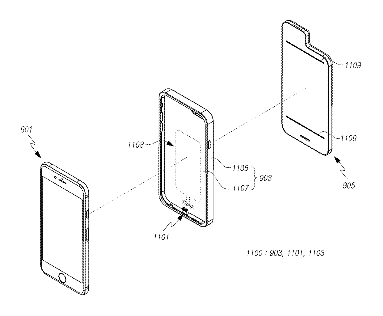
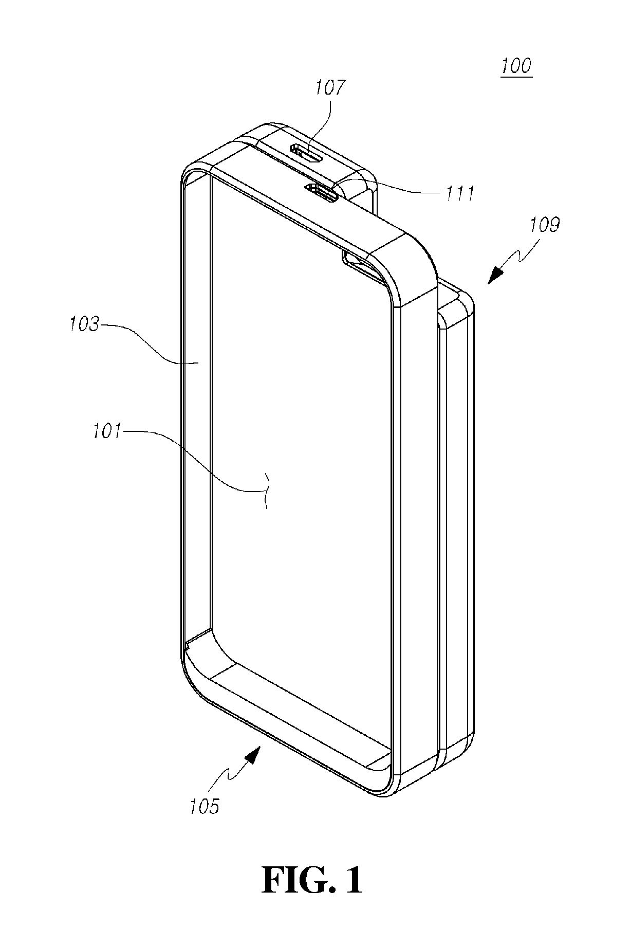
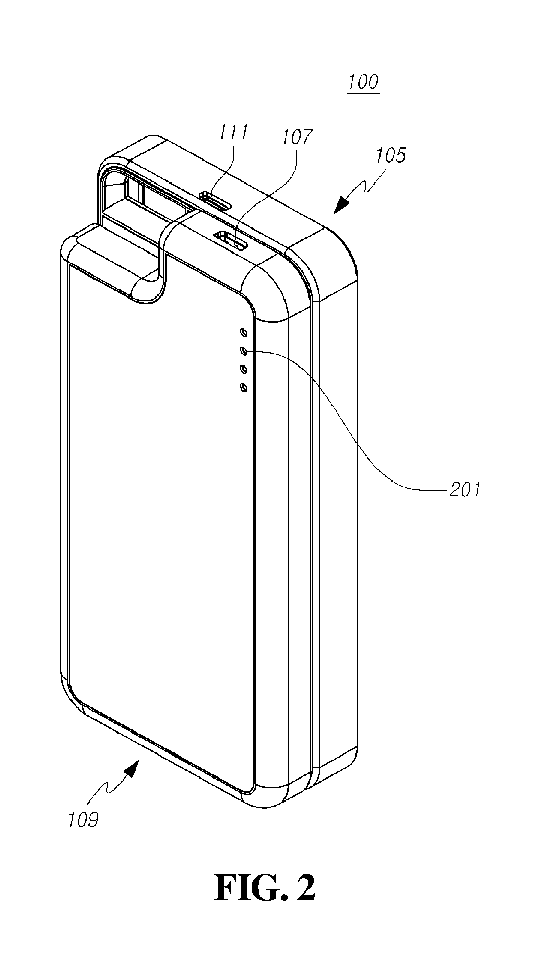
Provided herein is a portable charging case module. The portable charging case module includes a case part and an auxiliary battery part. The case part includes a body configured such that an accommodation recess is formed in the front thereof to be detachably combined with a terminal, a charging coil provided in the body and configured to wirelessly charge the terminal, and a first terminal unit formed in the rear of the body and configured to be electrically or data-wise connected to the terminal. The auxiliary battery part is detachably combined with the rear of the case part, and includes a second terminal unit configured to be electrically connected to the first terminal unit in the front of the auxiliary battery part facing the rear of the case part, and a connection port configured such that a connector connected to an external power source is inserted thereinto.

Description

BACKGROUND1. Technical Field[0001]The present invention relates to a portable charging case module.2. Description of the Related Art[0002]In general, the number of users of portable devices, such as mobile phones, etc., has been increasing. Recently, the use of smartphones that provide large-sized liquid crystal screens has also rapidly increased.[0003]Accordingly, various types of batteries for supplying power to smartphones have been developed. However, problems arise in that the power of these batteries is discharged faster than that of the batteries of conventional mobile phones due to large power consumption attributable to an increase in the size of the liquid crystal screens of smartphones and smartphones cannot be used in an emergency due to the full discharge of the batteries.[0004]To overcome these problems, Korean Patent No. 1174674 discloses charging devices using electromotive force. Of these charging devices, a case-type mobile phone charger includes a case body config...

Claims


Application Information

Patent Timeline
Patent Type & Authority Patents(United States)
IPC IPC(8): H04B1/3888H04M1/02H02J50/10H02J7/00H02J7/02
CPCH04B1/3888H02J7/0044H04M1/0202H02J50/10H02J7/025H02J50/12H04M1/0262H04M1/0274H04M1/185H02J7/0048A45C11/00A45C2011/002H02J7/342A45C13/002A45C13/1069H02J7/0047
Inventor JEON, JEONG HYEON
Owner KOREA ELECTRONICS TECH INST
Features
  • Generate Ideas
  • Intellectual Property
  • Life Sciences
  • Materials
  • Tech Scout
  • Unparalleled Data Quality
  • Higher Quality Content
  • 60% Fewer Hallucinations
Learn More