Non-contact voltage detector

a detector and non-contact technology, applied in the direction of electrical testing, measurement devices, instruments, etc., can solve the problems of difficult to see, battery draining quickly, source of electrical voltage located in a dark place, etc., and achieve the effect of preserving battery life and lowering the power consumption ra

Active Publication Date: 2018-09-11
KLEIN TOOLS INC
View PDF6 Cites 5 Cited by
  • Summary
  • Abstract
  • Description
  • Claims
  • Application Information

AI Technical Summary

Benefits of technology

[0005]The present disclosure is directed to a non-contact voltage detector with an integrated flashlight in which the flashlight and the voltage detector can be powered independently. The detector further includes a microprocessor controlled power-down system, which turns off the flashlight system and the voltage detector independently after predetermined and resettable time periods, and which prevents the voltage detector from powering down while the flashlight is lit.
[0006]The device in accordance with the present disclosure addresses many of the issues apparent in the prior art devices. The voltage detector can be powered on independently of the flashlight, which results in a much lower rate of power consumption and preserves battery life. The voltage detector automatically powers down after a predetermined time period, and the time period resets whenever voltage is detected by the tester. The flashlight can also be powered up independently of the voltage detector, and since it will not be on at all times when the voltage detector is in use, a much brighter and more powerful illumination source is used without high battery drain, and will power down automatically after a predetermined time period. A microprocessor controls the power systems and automatic timeouts, and in addition ensures that the voltage detector does not power down while the flashlight is on.

Problems solved by technology

Often, the source of electrical voltage is located in a dark place and difficult to see, such as within a wall, ceiling, or panel box.
The device of Chun will remain active until it is turned off, so the operator can rely on its readings during use, which can cause the battery to drain quickly.
Such systems, however, can shut-off the detector while the user believes it to be on, which may lead to inaccurate readings.

Method used


Image

  • Non-contact voltage detector
  • Non-contact voltage detector
  • Non-contact voltage detector

Examples


Embodiment Construction

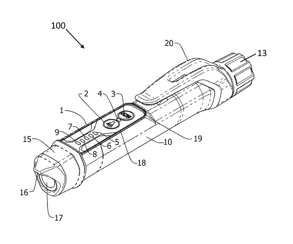
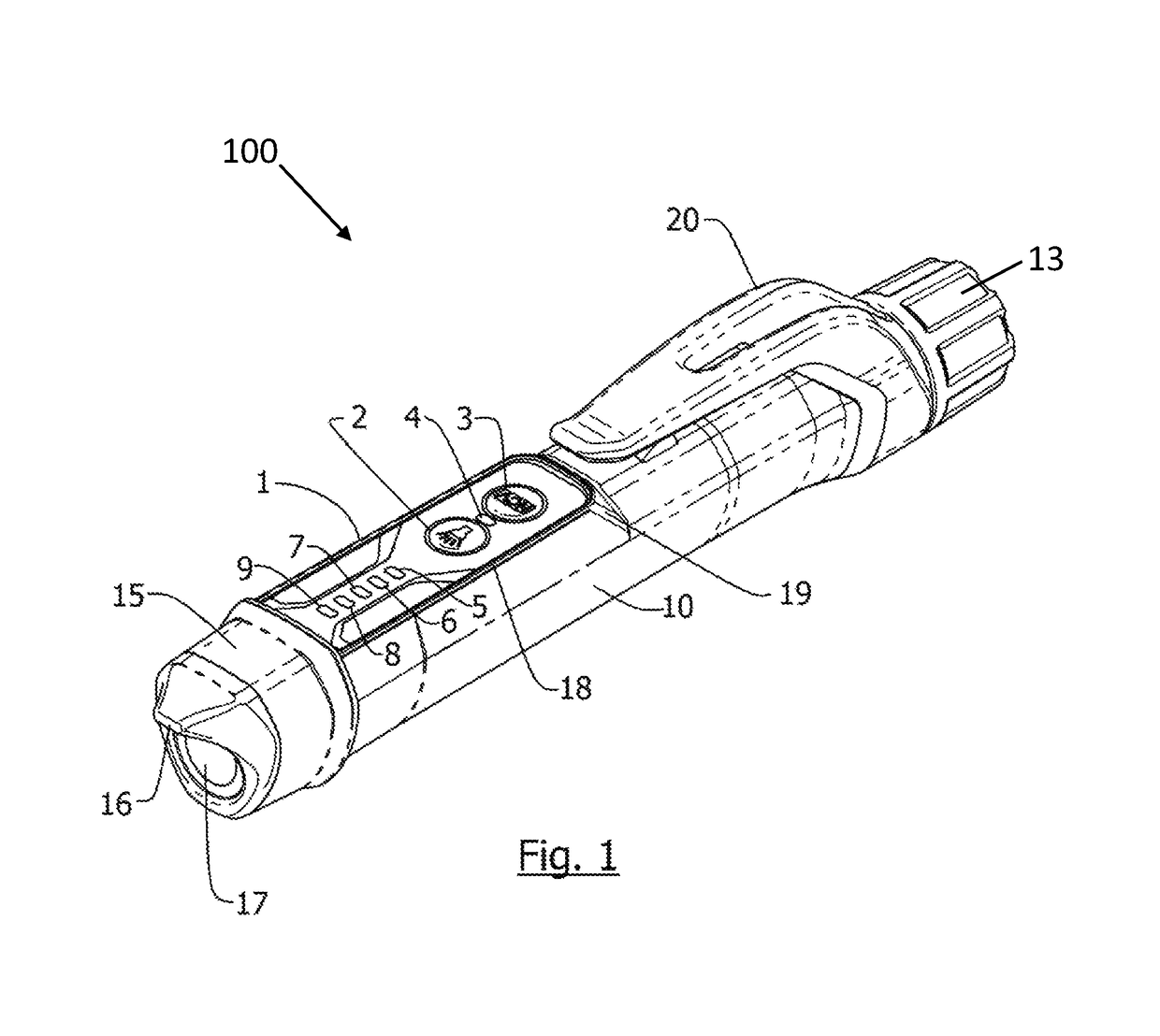
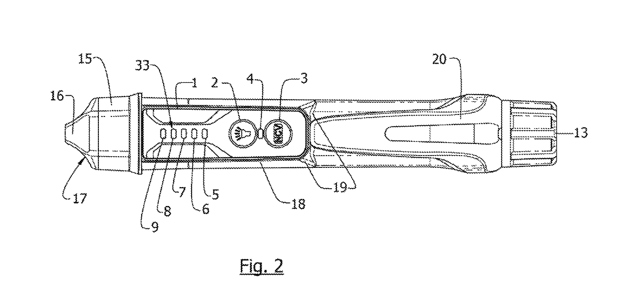
[0013]A preferred embodiment in accordance with the disclosure is depicted in the accompanying figures. A detector 100 in accordance with the disclosure is shown in FIG. 1 from a perspective view. The detector 100 includes a generally cylindrical hollow body 10 with an open end cap 13 and a tool end cap 15. The tool end cap 15 is generally constructed of translucent plastic and features a sensor protrusion 16 and a transparent flashlight lens 17. On the forward half of the cylindrical hollow body 10 and aligned with the sensor protrusion 16 is a user interface panel 1, which rests on a raised surface 18 supported by extended walls 19 rising out of the cylindrical hollow body 10. Between the cylindrical hollow body 10 and the open end cap 13 is positioned a pocket clip 20 for affixing the device to various surfaces, such as a shirt pocket. During use, the user may grasp the detector 100 from the body 10 and use fingers to operate the controls on the user interface panel 1, as well as...


PUM


Abstract

A voltage detector includes a cylindrical hollow body housing including an open end and a tool end. An internal circuit assembly includes a voltage sensing loop, a flashlight, and a microprocessor. The internal circuit assembly is disposed inside the cylindrical hollow body housing. The voltage sensing loop is configured to detect voltage without contacting a detected voltage, and the microprocessor is configured to control power to the flashlight via a flashlight power button independently from power to the voltage sensing loop via a voltage detector button.

Description

CROSS-REFERENCE TO RELATED APPLICATION[0001]This patent application claims the benefit of U.S. Provisional Patent Application No. 62 / 136,125, filed Mar. 20, 2015, which is incorporated by reference.FIELD OF THE DISCLOSURE[0002]The present disclosure relates to non-contact voltage detectors and, more particularly, to non-contact voltage detectors that include a flashlight.BACKGROUND OF THE DISCLOSURE[0003]Non-contact voltage detectors are well known in the field of electrical work, and are used routinely by electricians, utility workers, homeowners, and others who work near electrical equipment to provide a visual and / or audible indication that an electrical component is energized with electrical voltage. Often, the source of electrical voltage is located in a dark place and difficult to see, such as within a wall, ceiling, or panel box. Thus, it is advantageous for a non-contact voltage detector to include both a means of illuminating the area to be tested and a means to alert the u...

Claims


Application Information

Patent Timeline
Patent Type & Authority Patents(United States)
IPC IPC(8): G01R1/07G01R31/36G01R1/067G01R19/155
CPCG01R31/362G01R1/06788G01R19/155G01R1/07G01R29/0857G01R31/3835
Inventor KUHN, BRUCE
Owner KLEIN TOOLS INC
Why Eureka
Try Eureka