Latch valve and flow control device using the same

a technology of latch valve and flow control device, which is applied in the direction of fluid pressure control, process and machine control, instruments, etc., can solve the problems of difficult for self-generation bidets to continuously or repeatedly use electricity, and the amount of electricity generated by the introduced water is too small to operate the solenoid valve b, etc., to achieve a simple structure, low power consumption, and minimum power

Active Publication Date: 2013-01-31
WOONGJIN COWAY
View PDF7 Cites 15 Cited by
  • Summary
  • Abstract
  • Description
  • Claims
  • Application Information

AI Technical Summary

Benefits of technology

[0018]The latch valve capable of controlling a flow rate with a simpler structure at a low rate of power consumption, and the flow control device can be provided.
[0019]In addition, the latch valve can be operated without causing an error and consume minimum power, and the flow control device can be provided.

Problems solved by technology

In this case, however, the amount of electricity generated by the introduced water is too small to operate the solenoid valve 1.
In particular, it may be difficult for the self-generation bidet to continuously or repeatedly use electricity, so the valve is required to be more reliably operated.

Method used


Image

  • Latch valve and flow control device using the same
  • Latch valve and flow control device using the same
  • Latch valve and flow control device using the same

Examples


Embodiment Construction

[0027]Hereinafter, a latch valve and a flow control device using the latch valve will now be described with reference to the accompanying drawings.

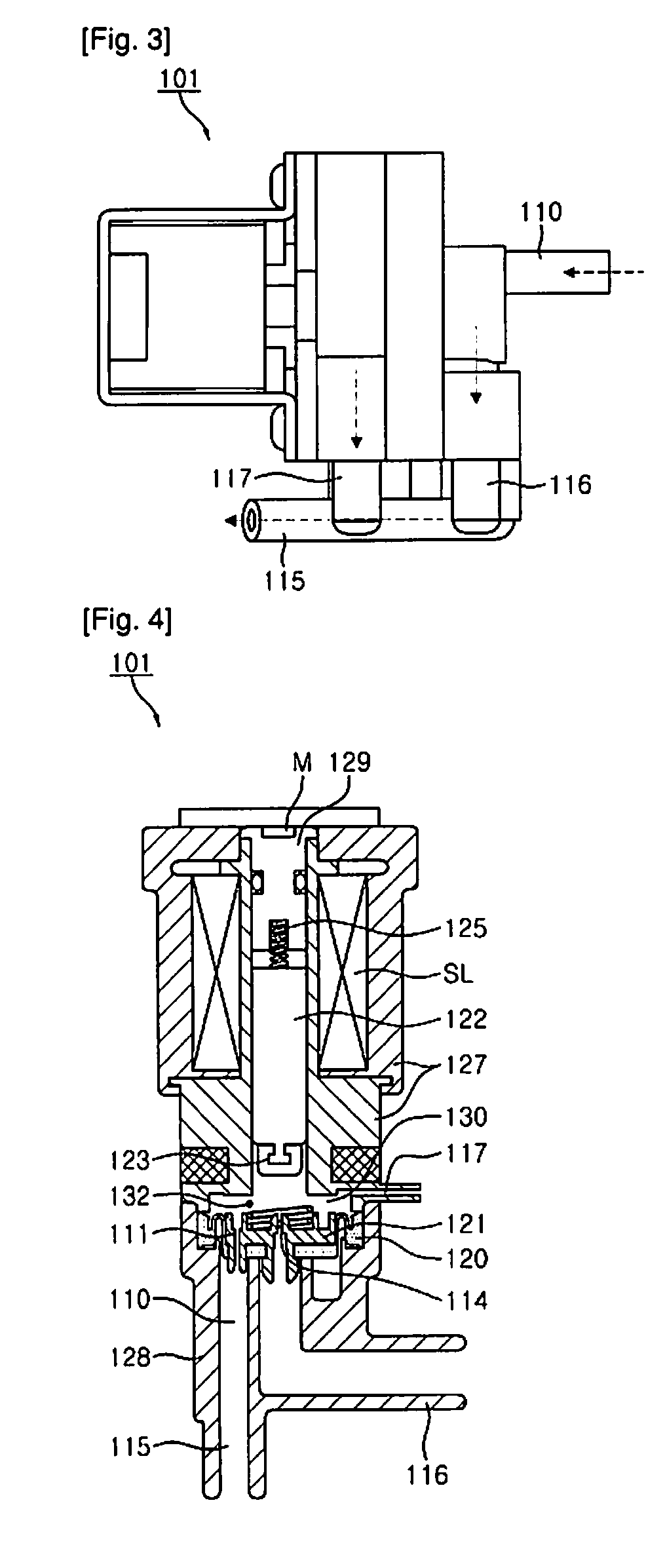
[0028]FIG. 3 is a plan view of a latch valve according to an exemplary embodiment of the present invention. A latch valve 101 includes a single inflow path 110, two outflow paths 116 and 117, and an outlet path 115 in which the two outflow paths 116 and 117 meet.

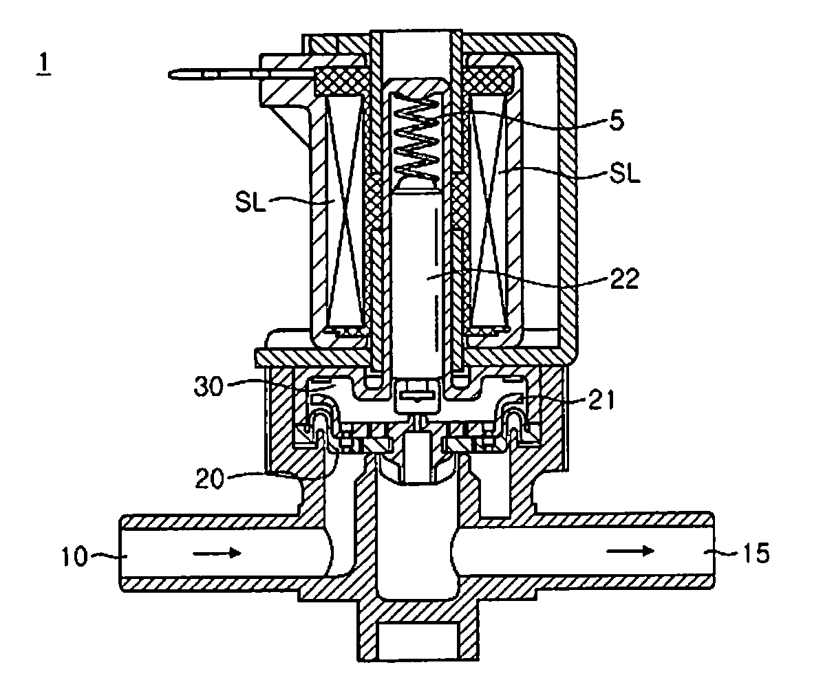
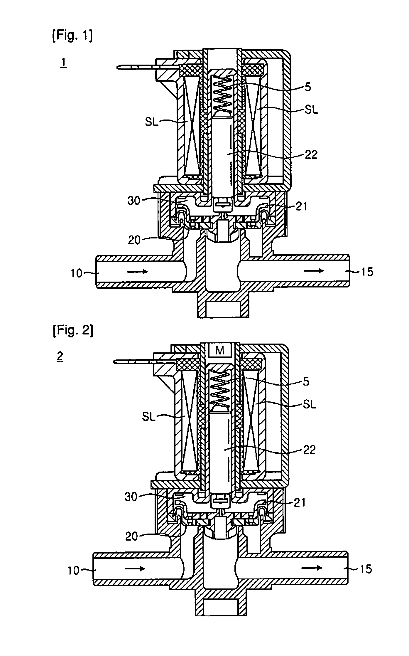
[0029]FIG. 4 is a sectional view of the latch valve according to an exemplary embodiment of the present invention. As shown in FIG. 4, a coil is wound on a solenoid SL at an inner side of a housing 127 in the latch valve 101. A plunger 122 and an iron core 129 are disposed at an inner side of the solenoid SL. A permanent magnet M is disposed at an upper portion of the iron core 129. A spring 125 is disposed in the iron core 129, and in this case, the spring 125 is disposed to push the plunger 122 toward an outlet 114.

[0030]A lower housing 128 includes an inflow path 110 and a firs...


PUM


Abstract

There are provided a latch valve consuming less power, having a simpler structure, and guaranteeing reliable valve operation, there is provided a flow control device comprising a plurality of latch valves connected in series, and the second to the last latch valves, among the latch valves connected in series, include an additional outflow path constantly communicating with a space part between a support body and a plunger, respectively, to allow water from an inlet to constantly flow out to the additional outflow paths.

Description

TECHNICAL FIELD [0001]The present invention relates to a structure of a latch valve capable of controlling a flow rate and a flow control device using the latch valve, and more particularly, to a latch valve for minimizing power consumption and a flow control device using the same.BACKGROUND ART [0002]In general, a flow control device uses a stepping motor or a plurality of solenoid valves to control a flow rate. For example, power is supplied, so the solenoid valves or the stepping motor is operated by using the supplied power to control a flow rate.[0003]The related art bidet controls a flow rate by using a solenoid valve as shown in FIG. 1. In the solenoid valve 1, a plunger 22 is usually in contact with a support body 21 of a diaphragm 20 by virtue of an elastic force of a spring 5 to block an outlet path 15, and when electricity is applied to a solenoid SL, the plunger 22 is lifted up by a magnetic force generated from the solenoid SL, allowing water introduced from an inflow p...

Claims


Application Information

Patent Timeline
Patent Type & Authority Applications(United States)
IPC IPC(8): F17D1/00F16K31/02
CPCF16K31/404F16K31/082Y10T137/86928Y10T137/87917
Inventor YUN, YOUNG-SANGPARK, MAN-UKKWON, SUN-DUGJIN, SUNG-WORLJEONG, JI-HYE
Owner WOONGJIN COWAY
Why Eureka
Try Eureka