
Drive device

a drive device and drive shaft technology, applied in the direction of friction gearings, toothed gearings, dynamo-electric machines, etc., can solve the problems of small overall outside diameter of the drive device, motors with lower power ratings, and electric motors with smaller diameters, etc., to achieve the effect of easy and efficient hand-held operation

Inactive Publication Date: 2011-03-08
STABILUS
View PDF13 Cites 15 Cited by
  • Summary
  • Abstract
  • Description
  • Claims
  • Application Information

AI Technical Summary

Benefits of technology

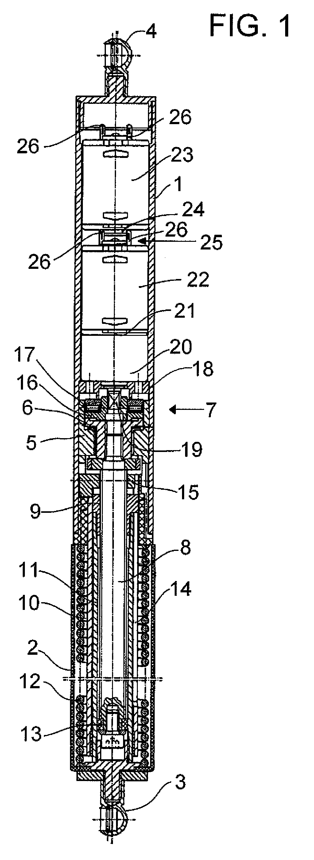
[0010]The overall power of the electric drive of the drive device is distributed over a plurality of electric motors. As a result, these motors can have lower power ratings and the electric motors will have smaller diameters. Thus, the area of the drive device in which the electric motors are installed can have a correspondingly small outside diameter. In addition, the additional components of the drive device can be easily provided with a small outside diameter, and the outside diameter of the drive unit is determined by the outside diameter of the motor area. As a result, the overall outside diameter of the drive device will be small.
[0028]In other embodiments, the threaded spindle is a multi-thread spindle preferably with a lead in the range of about 10-24 mm so that the device can be operated easily and efficiently by hand.

Problems solved by technology

As a result, these motors can have lower power ratings and the electric motors will have smaller diameters.
As a result, the overall outside diameter of the drive device will be small.

Method used


Image

  • Drive device
  • Drive device

Examples


Embodiment Construction

[0032]With reference to the FIGURE, the device shown therein has a housing tube 1 made of a conductive material, such as steel, on which a jacket tube 2 is guided in a telescoping manner.

[0033]A first ball socket 3 is provided on an end of the jacket tube 2 opposite the housing tube 1, and a second ball socket 4 is provided on the end of the housing tube 1 opposite the jacket tube 2. These sockets 2, 4 make it possible to hinge the drive device to a stationary body component of a motor vehicle and to a movable component of the motor vehicle, such as a hatch of the vehicle.

[0034]A first bearing part 5 is permanently inserted in the end area of the housing tube 1 facing the jacket tube 2, in which a first clutch part 6 of a friction clutch 7 is rotatably supported. The clutch part is seated firmly on one end of a threaded spindle 8 projecting into the jacket tube 2.

[0035]A spindle nut 9 is threaded onto the threaded spindle 8 but is mounted non-rotatably with respect to the housing tu...


PUM


Abstract

A drive device for a hatch of a motor vehicle, wherein a spindle drive is provided with a threaded spindle and a spindle nut mounted on the threaded spindle, by which drive the first fastening element and the housing tube can be driven axially relative to each other. The spindle drive can be rotatably driven by an electric motor, where the output shaft of the motor can rotate the threaded spindle or a connecting component of a clutch. The spindle drive can be rotatably driven by two or more series-connected electric motors.

Description

BACKGROUND OF THE INVENTION[0001]1. Field of the Invention[0002]The present invention generally relates to the field of door openers and, more particularly, to a drive device for a hatch of a motor vehicle.[0003]2. Description of the Related Art[0004]Conventional drive devices for the hatch of a motor vehicle typically include a first fastening element that can be connected to a stationary component or to a movable component and a housing tube that is located at an end of the drive device opposite to the first fastening element. The housing tube is able to move axially relative to the first fastening element and has a second fastening element on the end opposite the first fastening element, where it is possible to connect this second element to the movable component or to the stationary component.[0005]The drive device also includes a spindle drive that comprises a threaded spindle and a spindle nut that is mounted on the threaded spindle. The spindle drive permits the first fasteni...

Claims


Application Information

Patent Timeline
Patent Type & Authority Patents(United States)
IPC IPC(8): F16H29/20E05F11/24
CPCE05F15/622H02K7/06E05F1/1058E05Y2201/72E05Y2900/546Y10T74/18088Y10T74/18576Y10T292/1079Y10T292/1082
Inventor BOCHEN, MARIANMINTGEN, ROLFSCHINDLATZ, CHRISTIANSCHUTTLER, OLIVER
Owner STABILUS
Learn More