Drive device

Inactive Publication Date: 2008-09-11
STABILUS
View PDF8 Cites 18 Cited by
  • Summary
  • Abstract
  • Description
  • Claims
  • Application Information

AI Technical Summary

Benefits of technology

[0037]The components of the drive device can be protected from dirt and damage by designing the housing tube and the jacket tube so that they can telesc

Problems solved by technology

This leads to a drive device which

Method used


Image

  • Drive device
  • Drive device
  • Drive device

Examples


Embodiment Construction

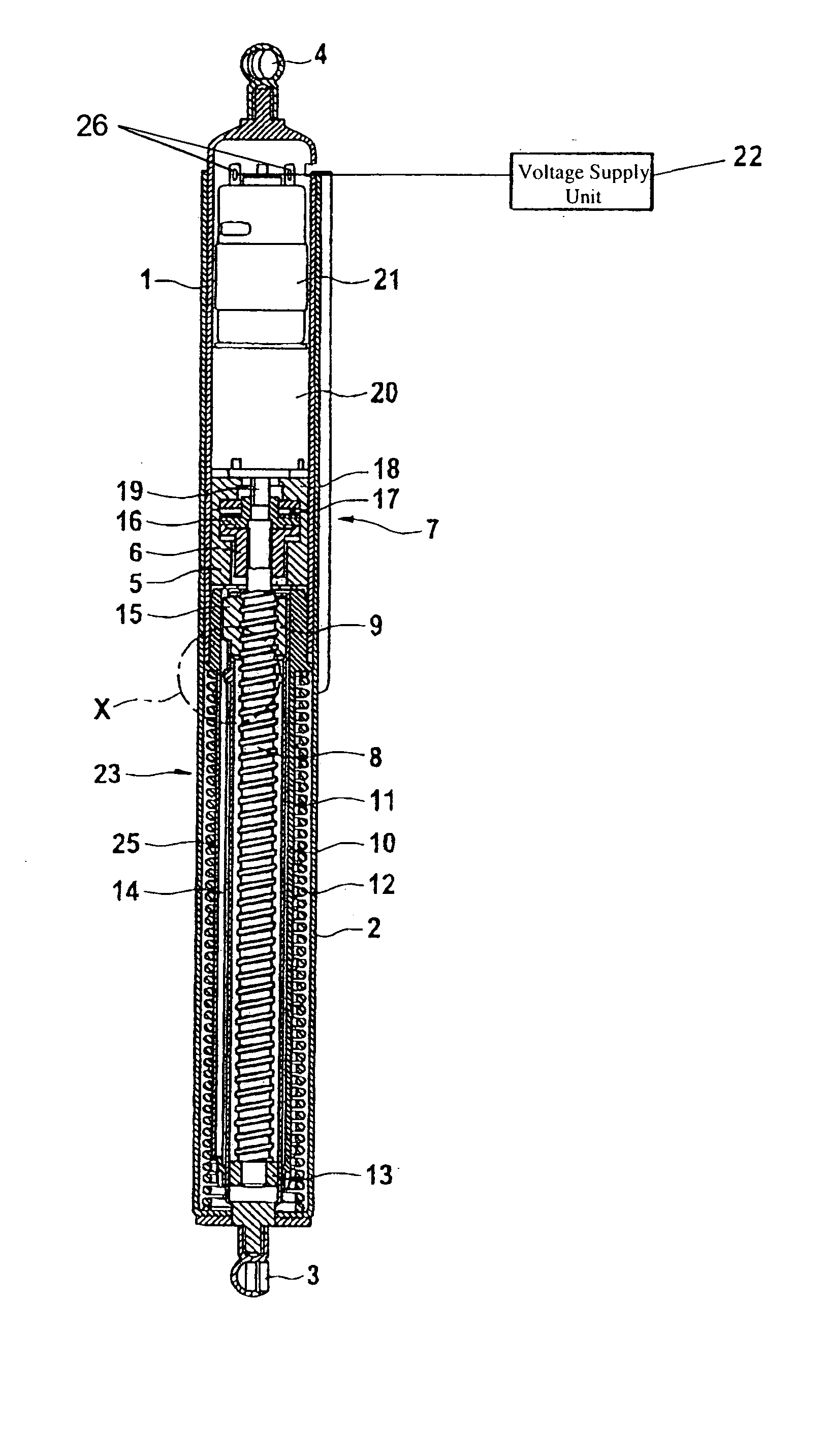
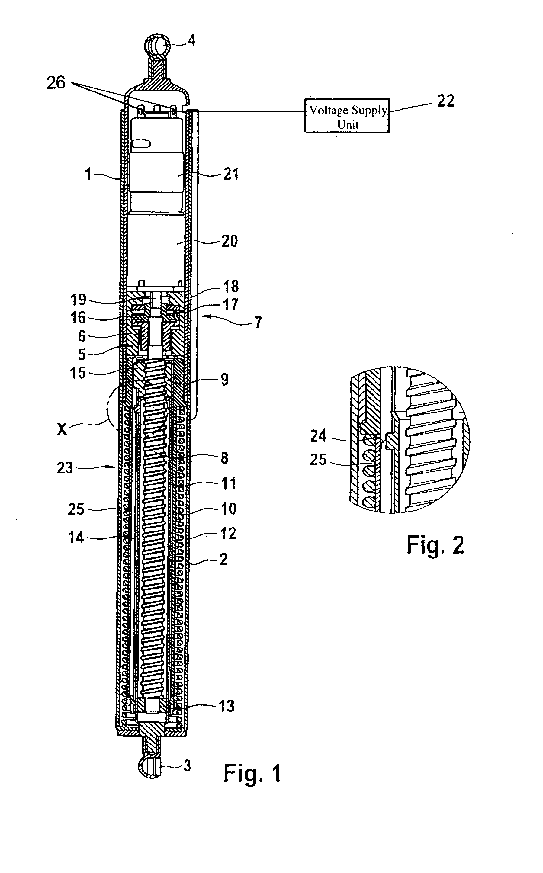
[0044]The drive device shown in FIG. 1 has a housing tube 1, on which a jacket tube 2 is guided in a telescoping manner. On the end of the jacket tube 2 opposite the housing tube 1, a first ball socket 3 is provided, and on the end of the housing tube 1 opposite the jacket tube 2, a second ball socket 4 is provided. These sockets 3, 4 make it possible to hinge the drive device to a stationary body component of a motor vehicle and to a movable component of the motor vehicle, such as a hatch. In the end area of the housing tube 1 facing the jacket tube 2, a first bearing part 5 is permanently inserted, in which a first clutch part 6 of a friction clutch 7 is rotatably supported. The clutch part 6 is seated firmly on one end of a threaded spindle 8 projecting into the jacket tube 2. A spindle nut 9 is threaded onto the threaded spindle 8 but is unable to rotate with respect to the housing tube 1.

[0045]The spindle nut 9 is connected to one end of a spindle tube 11, which coaxially surro...


PUM


Abstract

A drive device for a motor vehicle, including a first fastening element connectable to one of a stationary component and a movable component of the motor vehicle; a housing tube comprising a first end facing away from the first fastening element, and a second fastening element on the first end, the second fastening element being connectable to the other of a stationary component and a movable component of the motor vehicle; a spindle drive comprising a threaded spindle; and a spindle nut mounted on the threaded spindle; and an electric motor for driving the threaded spindle in rotation. The spindle drive is configured to move the first fastening element and the housing tube away from each other in an axial movement. When energized the electric motor drives the threaded spindle in rotation with a torque which decreases over the course of the axial movement.

Description

BACKGROUND OF THE INVENTION[0001]1. Field of the Invention[0002]The invention relates to a drive device especially for a hatch of a motor vehicle. The drive device includes a first fastening element which can be connected to a stationary component or to a movable component; a housing tube located at the end opposite the first fastening element which is able to move axially relative to that first fastening element and has a second fastening element on the end opposite the first fastening element, it being possible to connect this second element to the other of the stationary component or the movable component; and a spindle drive which includes a threaded spindle and a spindle nut mounted on the threaded spindle, by means of which drive the first fastening element and the housing tube can be driven axially relative to each other. The spindle drive can be driven in rotation by an electric motor, the shaft of which can rotate the threaded spindle or a clutch component of a clutch.[0003...

Claims


Application Information

Patent Timeline
IPC IPC(8): E05F15/12
CPCE05Y2400/31E05Y2400/328E05F15/622E05Y2900/546E05Y2800/748E05Y2400/614
Inventor BOCHEN, MARIANMINTGEN, ROLFSCHINDLATZ, CHRISTIAN
Owner STABILUS
Why Eureka
Try Eureka