Method of and apparatus for detecting and controlling bilge water in a sea vessel

a sea vessel and bilge water technology, applied in the field of boats and other watercraft, can solve the problems of water intrusion into the hull of boats, the tendency of most boats to take on a certain amount of water,

Inactive Publication Date: 2010-02-16
WALDECKER DONALD E
View PDF14 Cites 17 Cited by
  • Summary
  • Abstract
  • Description
  • Claims
  • Application Information

AI Technical Summary

Benefits of technology

[0018]Accordingly, it is a general object of the present invention to provide an improved bilge water level monitor, alert and control system for boats and other vessels.
[0019]It is another object of the present invention to provide a method of and apparatus for detecting excessive leakage of water into the bilge of a sea vessel and, in response to excessive water in the bilge, triggering an alarm to notify the operator or others.
[0020]It is another object of the present invention to provide an improved bilge water monitor, alert and control system for boats and other vessels that provides means for reducing the likelihood of exhausting battery power in the event of a significant seawater leakage problem.
[0021]It is another object of the present invention to provide an improved bilge pump monitor and alert system for boats and other vessels in which switching to manual operation of the pump does not de-energize the automatic switch and the alarm / monitoring system.
[0022]It is another object of the present invention to provide an improved bilge pump monitor and alert system for boats and other vessels in which the electrical power rating of the monitoring circuitry components is relatively low, thereby reducing the size (footprint and / or volume) and weight of those components relative to prior bilge pump monitoring and alert systems.
[0024]It is another object to provide a variation of the present invention in which the water level detection and control circuitry operates with sufficiently low amperage to substantially eliminate the hazard of spark-induced combustion, even in the event of circuitry wiring damage in the vicinity of the bilge.

Problems solved by technology

As is well known, most boats, regardless of the material or construction and fabrication thereof, have a tendency to take on a certain amount of water when floating in a body of water.
However, generally speaking, such causes of water intrusion into the hulls of boats include, among other causes, plumbing failures, seepage through the hull material or joints formed between elements of the hull, leakage or small flaws in the hull integrity, plumbing failures in potable water tanks or in unlimited dock-supplied potable water lines, failures of engine cooling systems and failure of seals utilized with various “through-the-hull” fittings or couplings as well as rain which runs into the bilge.
In the event that inflow of seawater into the bilge is greater than the capacity of the bilge pump, or in the event that electric power is exhausted or otherwise cut off, or in the event of bilge pump failure before the inflow of water is controlled, the level of seawater will rise in the bilge with catastrophic results.
A problem with prior bilge monitoring and pumping systems is that continuous running of the pump not only means that there is likely a significant leakage problem, but the continuous running of the pump can cause the battery to run down or pump failure to occur, thus rendering the battery / pump system inoperable.
Another problem of such prior systems is that switching to manual operation of the pump typically involves bypassing and / or de-energizing the automatic switch and the alarm / monitoring system.
Although manual turning “on” of the pump addresses the symptom (i.e., too much water in the bilge), it does not address the problem (e.g., leaking hull).
Another problem of such prior systems is that the electrical power rating of the monitoring circuitry components is typically proportional to the size (footprint and / or volume) and weight of those components.
That is, typically, the higher the power rating of the electrical components, the bigger and heavier those components are, and the heavier gauge of the associated wiring and connectors.
Another problem of such prior systems is that manual pump switches are typically located at the bridge of the vessel, whereas the battery is (or batteries are) typically located below deck, and the pump necessarily is located at the bilge.
Because such pumps often have high power ratings, it is necessary in such prior systems to run heavy gauge (i.e., relatively expensive, bulky and heavy) power lines long distance throughout the vessel.
Another problem is that the electrical wiring associated with water level-detecting float switches in such prior systems is often exposed to corrosive and / or volatile liquids and / or gasses in the bilge.
Such exposure often compromises the integrity of the electrical connections and / or wiring, resulting in system maintenance and operation problems.
Such exposure can also subject the vessel to fire and explosion hazards.
Another problem is that the water level detection and control circuitry in such prior systems typically involves relatively high amperage electrical transmission, in the event of damage to the wiring insulation in such systems, there is a risk of fire and / or explosion due to the possibility of spark ignition of gases in the bilge.

Method used


Image

  • Method of and apparatus for detecting and controlling bilge water in a sea vessel
  • Method of and apparatus for detecting and controlling bilge water in a sea vessel
  • Method of and apparatus for detecting and controlling bilge water in a sea vessel

Examples


Embodiment Construction

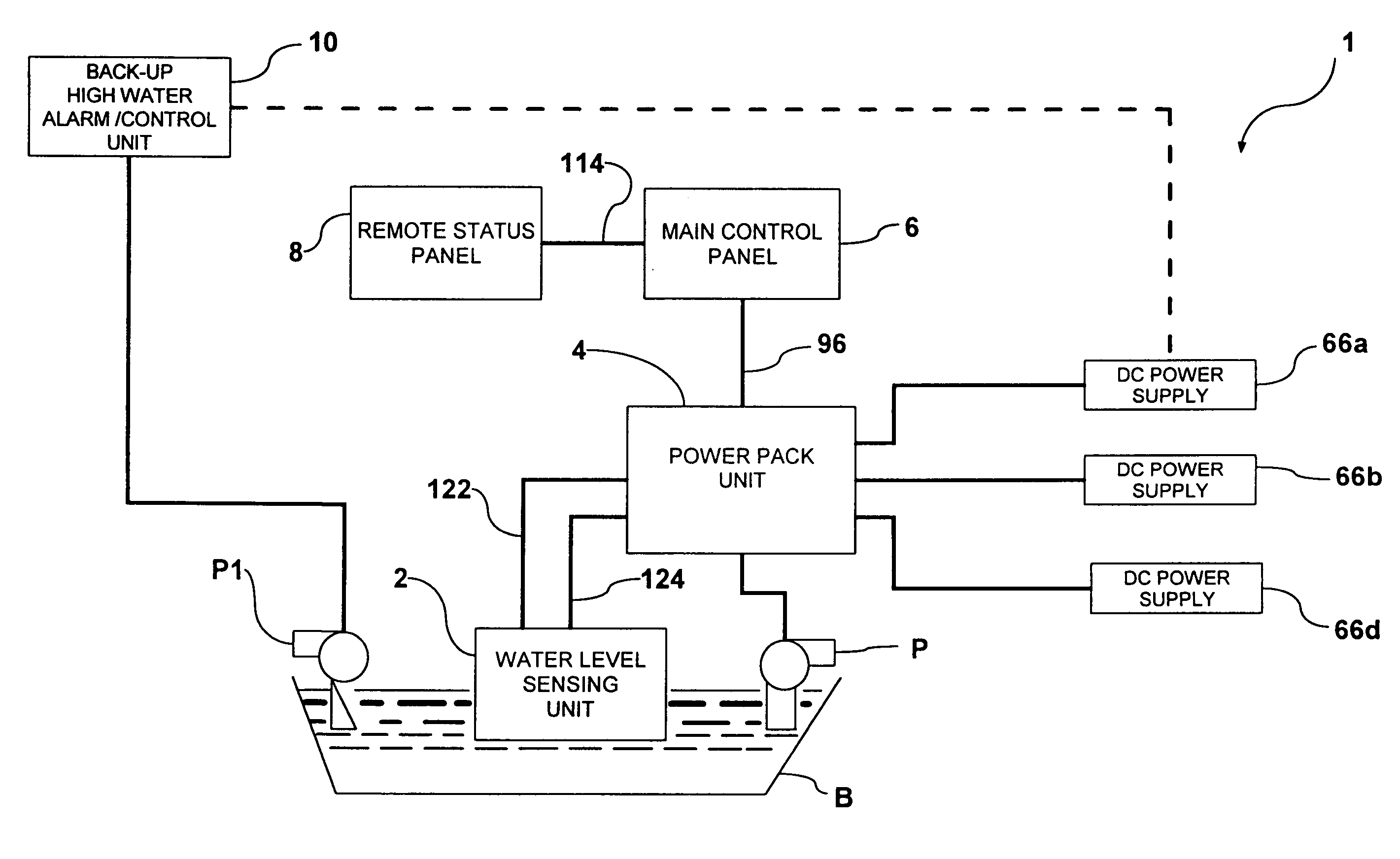
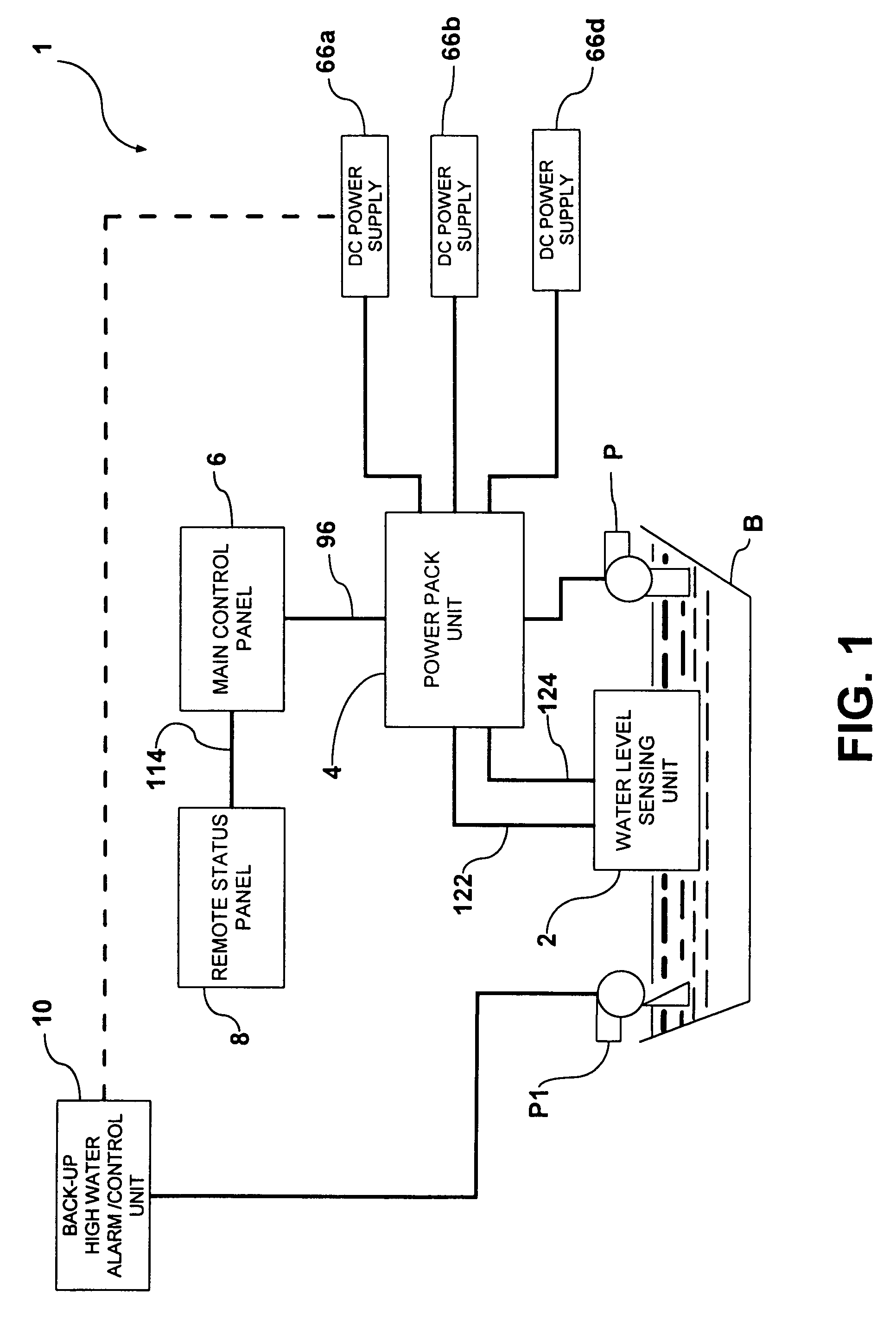
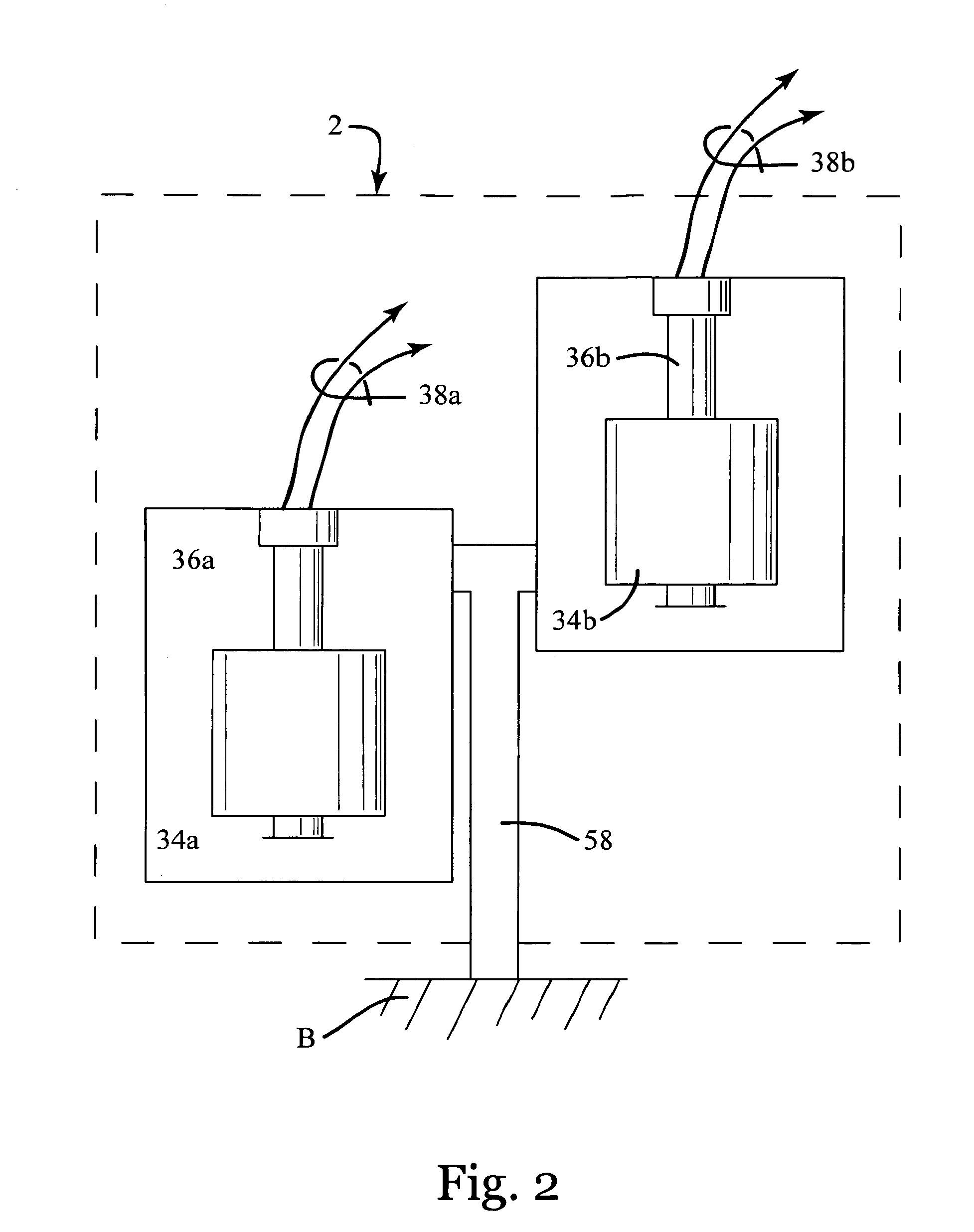
[0142]Referring to FIGS. 1 and 18, a bilge water level monitoring, alerting and control system (generally designated 1 in the drawings and herein also referred to as the “Monitoring System”) for boats and other vessels is described. The Monitoring System 1 generally comprises a water level sensing assembly 2 that is electrically connected to a power pack unit 4 and a main control panel 6. A remote status panel 8 is electrically connected to the main control panel 6. Means are provided for connecting the power pack unit 4 to one or more external DC power supplies 66 and to one or more external pump(s) (P). In a modified embodiment of the invention an optional back-up alarm unit 10 is also electrically connected, (either directly, as shown in FIG. 1. or indirectly via the power pack unit 4), to the DC power supply 66.

[0143]The Monitoring System 1 provides means to monitor the level of water in the bilge (B) of a vessel, to activate one or more pumps (P) for the removal of such water f...


PUM


Abstract

An improved bilge water level monitor, alert and control system for boats and other vessels. The system provides a method of detecting excessive leakage of water into the bilge and in response to the excessive water in the bilge, triggering an alarm to notify the operator and others and energizes bilge pumps to remove the excessive water. The system is designed with many redundancies in the sub elements and subsystems for safety. The system provides a means for reducing the likelihood of exhausting battery power in the event of a significant seawater leakage problem. The electrical power rating of the monitoring circuitry components is relatively low, thereby reducing the size and weight of those components relative to prior bilge pump monitoring and alert systems. There is no electrical wiring exposed to bilge water during system operation thereby reducing damage to the wiring components. The water level detection and control circuitry operates with sufficiently low amperage to substantially eliminate the hazard of spark-induced combustion.

Description

REFERENCES CITED[0001]U.S. PATENT DOCUMENTS3,757,317September 1973Kahn340 / 2444,341,178July 1982Price114 / 183 R4,551,068November 1985Boudreaux417 / 84,804,939February 1989Sale338 / 805,076,763December 1991Anastos417 / 445,324,170June 1994Anastos417 / 125,357,247October 1994Marnel340 / 9845,506,564April 1996Hargest340 / 450.26,005,483December 1999West340 / 6186,218,948April 2001Dana340 / 6046,473,004October 2002Smull340 / 984CROSS-REFERENCES[0002]The present application is filed with reference to the previously filed provisional patent application, filed on Feb. 4, 2005, entitled “Method of and Apparatus for Detecting and Controlling Bilge Water in a Sea Vessel”, Inventor Donald E. Waldecker, Patent Agent Stephen E. Clark.BACKGROUND OF THE INVENTION[0003]1. Technical Field[0004]The present invention relates to boats and other watercraft and more particularly to systems operative to manage and control as well as monitor the operation of bilge pump systems therefore.[0005]2. Discussion of Related Art[0006...

Claims


Application Information

Patent Timeline
Patent Type & Authority Patents(United States)
IPC IPC(8): B63B13/00B63B29/16B63J4/00
CPCB63J4/004G08B21/20
Inventor WALDECKER, DONALD E.
Owner WALDECKER DONALD E
Why Eureka
Try Eureka