Al technical title is built by PatSnap Al team. It summarizes the technical point description of the patent document.
a technology for electric flat conductors and motor vehicles, which is applied to insulated conductors, flat/ribbon cables, cables, etc., can solve the problems of increased risk of damage to insulation, increased cycle times in bending processes, and damage to flat conductors, so as to improve resistance to mechanical bending operations, increase wall thickness, and increase wall thickness
Active Publication Date: 2018-09-11
AUTO KABEL MANAGEMENTGMBH
View PDF16 Cites 6 Cited by
Summary
Abstract
Description
Claims
Application Information
AI Technical Summary
This helps you quickly interpret patents by identifying the three key elements:
Problems solved by technology
Method used
Benefits of technology
[0009]It was recognised that in this way an electrical flat conductor can be provided that has an improved resistance in particular to shaping of the flat conductor by means of bending tools.
[0044]Owing to the reduction of the flat conductor core width installation space becomes free, which advantageously can be used in order correspondingly to increase the wall thickness of the insulation in this region so as to achieve a further improvement of the stability of the flat conductor in the region of the narrow sides. In this way the first and second teachings advantageously co-operate synergistically to improve the stability of the flat conductor, since a flat conductor can be made available that is neutral as regards installation space but is optimised as regards bending.
Problems solved by technology
With such shaping procedures there is the problem that the insulation of the flat conductor may be damaged as a result of the forces acting on the flat conductor, especially if comparatively soft insulating materials such as for example polyvinyl chloride (PVC) are used.
The risk of damage to the insulation is particularly great if the shaping is performed on a narrow side of the flat conductor.
This leads however to longer cycle times in the bending processes, so that the production costs of 3D-bent flat conductors would be increased.
Depending on the machine utilisation this procedure could even require the procurement of further bending devices, thereby also in addition incurring investment costs.
Method used
Image
Click on the blue label to locate the original text in one second.
Reading with bidirectional positioning of images and text.
Examples
Embodiment Construction
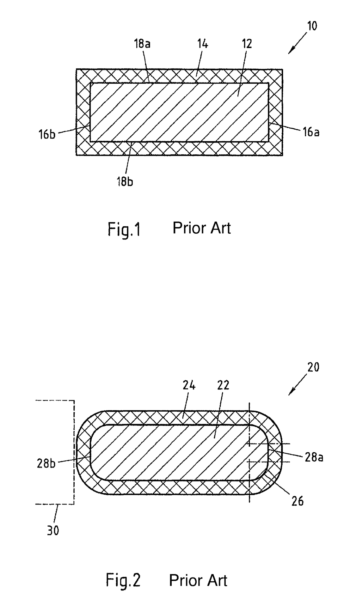
[0053]FIG. 1 shows a first electrical flat conductor 10 from the prior art in cross-section. The flat conductor has a flat conductor core 12 of conductive flat conductor material, such as for example an aluminium alloy, and an insulation 14 of an insulating material, such as for example polyvinyl chloride, encasing the flat conductor core 12.
[0054]The flat conductor core 12 has a rectangular cross-section, whose width is limited by two narrow sides 16a-b and whose height is limited by two broad sides 18a-b. The height of the flat conductor core 12 is in this case less than its width. With a rectangular cross-section the narrow sides 16a-b and broad sides 18a-b of the flat conductor core 12 respectively meet one another at right angles, so that the flat conductor core 12 has quite sharp edges. These sharp edges can severely stress the insulation 14, so that damage to the insulation 14 frequently occurs especially during a bend forming of the flat conductor 10.
[0055]In the prior art t...
PUM
Property
Measurement
Unit
height
aaaaa
aaaaa
thickness
aaaaa
aaaaa
thickness
aaaaa
aaaaa
Abstract
The invention relates to an electrical flat conductor (40, 60, 80, 100) for motor vehicles with a flat conductor core (42, 62, 82, 102) of electrically conductive flat conductor material and with an insulation of an insulating material encasing the flat conductor core (42, 62, 82, 102), wherein the height (Hk) of the flat conductor core (42, 62, 82, 102) is less than the width (Bk) of the flat conductor core, wherein the flat conductor core (42, 62, 82, 102) has at least one narrow side (46a-b, 68a-b, 86a-b, 106a-b), which limits the width of the flat conductor core (42, 62, 82, 102) on one side, wherein the at least one narrow side (46a-b, 68a-b, 86a-b, 106a-b) of the flat conductor core (42, 62, 82, 102) has at least in sections over the length of the flat conductor (40, 60, 80, 100) a partial surface (52a-b, 70a-b, 114a-b), whose contour in the cross-section of the flat conductor core (42, 62, 82, 102) forms a straight section (46a-b, 54a-b, 72a-b, 116a-b), which extends over a part of the height of the flat conductor core (42, 62, 82, 102), wherein the straight section (46a-b, 54a-b, 72a-b, 116a-b) extends over at least 75% of the height of the flat conductor core (42, 62, 82, 102). The invention furthermore relates to an electrical flat conductor (40, 60, 80, 100) for motor vehicles with a flat conductor core (42, 62, 82, 102) of electrically conductive flat conductor material and with an insulation (44, 64, 84, 104) of an insulating material encasing the flat conductor core (42, 62, 82, 102) , wherein the height (Hk) of the flat conductor core (42, 62, 82, 102) is less than the width (Bk) of the flat conductor core (42, 62, 82, 102) and wherein the insulation (44, 64, 84, 104) at least in sections over the length of the flat conductor (40, 60, 80, 100) on at least one side (46a-b, 48a-b, 68a-b, 86a-b, 88a-b, 106a-b, 108a-b) of the flat conductor core (42, 62, 82, 102) has a greater wall thickness than on at least one other side (46a-b, 48a-b, 68a-b, 86a-b, 88a-b, 106a-b, 108a-b) of the flat conductor core (42, 62, 82, 102).
Description
TECHNICAL FIELD[0001]The invention relates to an electrical flat conductor for motor vehicles with a flat conductor core of conductive flat conductive material and with an insulation of an insulating material encasing the flat conductor core, wherein the height of the flat conductor core is less than the width of the flat conductor core.BACKGROUND ART[0002]Such electrical flat conductors are used for example in the automotive industry as an alternative to round conductors. Owing to the flat geometry of the flat conductors these can be used for example in cases in which there is little space available for their installation, such as for example behind a cladding in the interior of a motor vehicle.[0003]Such a flat conductor includes a conductive flat conductor core, which extends in the longitudinal direction of the flat conductor and whose height (in cross-section) is less than its width. The flat conductor core is encased in an insulation in order to avoid undesirable electrical co...
Claims
Application Information
Patent Timeline
Application Date:The date an application was filed.
Publication Date:The date a patent or application was officially published.
First Publication Date:The earliest publication date of a patent with the same application number.
Issue Date:Publication date of the patent grant document.
PCT Entry Date:The Entry date of PCT National Phase.
Estimated Expiry Date:The statutory expiry date of a patent right according to the Patent Law, and it is the longest term of protection that the patent right can achieve without the termination of the patent right due to other reasons(Term extension factor has been taken into account ).
Invalid Date:Actual expiry date is based on effective date or publication date of legal transaction data of invalid patent.