Rotating electric machine and method of manufacturing same

a technology of rotating electric machines and rotating plates, which is applied in the direction of dynamo-electric machines, electrical apparatus, magnetic circuits, etc., can solve the problems of uneven surface of welds, peeling of weld-insulating parts, and uneven joint formation of uneven parts on the surface of welds, so as to enhance the adhesion force of weld-insulating parts and reduce the mechanical strength of welds. , the effect of forming the uneven

Active Publication Date: 2018-09-11
DENSO CORP
View PDF39 Cites 2 Cited by
  • Summary
  • Abstract
  • Description
  • Claims
  • Application Information

AI Technical Summary

Benefits of technology

[0010]If the protrusions of the uneven portion of the weld were dot-shaped as taught by Japanese Patent No. JP5510709B2, due to the repeated expansion and contraction of the weld and the weld-insulating member with temperature change, stress might concentrate on peripheral portions of the weld-insulating member which abut some of the protrusions. As a result, the adhesion force of the peripheral portions of the weld-insulating member to the weld might be lowered, causing the weld-insulating member to peel off from the weld. However, according to the exemplary embodiments, the protrusions of the uneven portion of the weld are annular-shaped. Therefore, even if the weld and the weld-insulating member repeat expansion and contraction with temperature change, stress concentration hardly occurs in the weld-insulating member. Moreover, according to the exemplary embodiments, the recesses of the uneven portion of the weld are also annular-shaped. Therefore, during the formation of the weld-insulating member, the molten material of the weld-insulating member is impregnated into the annular-shaped recesses of the uneven portion of the weld and solidified therein to form annular-shaped protrusions. Consequently, the annular-shaped protrusions of the weld-insulating member are respectively fitted in the annular-shaped recesses of the uneven portion of the weld. As a result, it becomes possible to more reliably suppress the adhesion force of the weld-insulating member to the weld from being lowered due to the repeated expansion and contraction of the weld and the weld-insulating member with temperature change; thus, it becomes possible to more reliably suppress the weld-insulating member from peeling off from the weld.
[0017]With any of the first, second and third methods, blow holes are formed neither on the surface of the weld nor inside the weld. Consequently, it becomes possible to reliably form the uneven portion on the surface of the weld without lowering the mechanical strength of the weld. As a result, it becomes possible to enhance the adhesion force of the weld-insulating member to the weld.

Problems solved by technology

However, in the rotating electric machine disclosed in the above patent document, the uneven portions of the joints are formed by the blow holes that are randomly created in the surfaces of the joints.
As a result, the adhesion force of the peripheral portions of the weld-insulating member to the weld might be lowered, causing the weld-insulating member to peel off from the weld.

Method used


Image

  • Rotating electric machine and method of manufacturing same
  • Rotating electric machine and method of manufacturing same
  • Rotating electric machine and method of manufacturing same

Examples


first embodiment

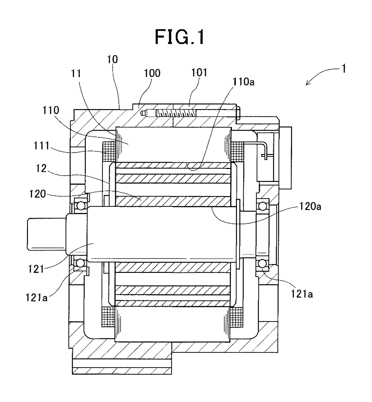
[0051]FIG. 1 shows the overall configuration of a rotating electric machine 1 according to a first embodiment.

[0052]In the present embodiment, the rotating electric machine 1 is configured as a motor-generator for use in a motor vehicle. Specifically, upon being supplied with electric power from a battery (not shown) of the vehicle, the rotating electric machine 1 functions as an electric motor to generate torque (or driving force) for driving the motor vehicle. Otherwise, upon being supplied with torque from an engine (not shown) of the vehicle, the rotating electric machine 1 functions as an electric generator to generate electric power for charging the battery.

[0053]As shown in FIG. 1, the rotating electric machine 1 includes a housing 10, a stator 11 and a rotor 12.

[0054]The housing 10 receives both the stator 11 and the rotor 12 therein and rotatably supports the rotor 12. The housing 10 is comprised of a pair of cup-shaped housing pieces 100 and 101 which are jointed together ...

second embodiment

[0081]A rotating electric machine 1 according to a second embodiment has almost the same structure as the rotating electric machine 1 according to the first embodiment. Accordingly, only the differences therebetween will be described hereinafter.

[0082]In the first embodiment, the uneven portions of the welds are formed by pressing the die M against the surfaces of the welds. In comparison, in the present embodiment, the uneven portions of the welds are formed by cutting the surfaces of the welds.

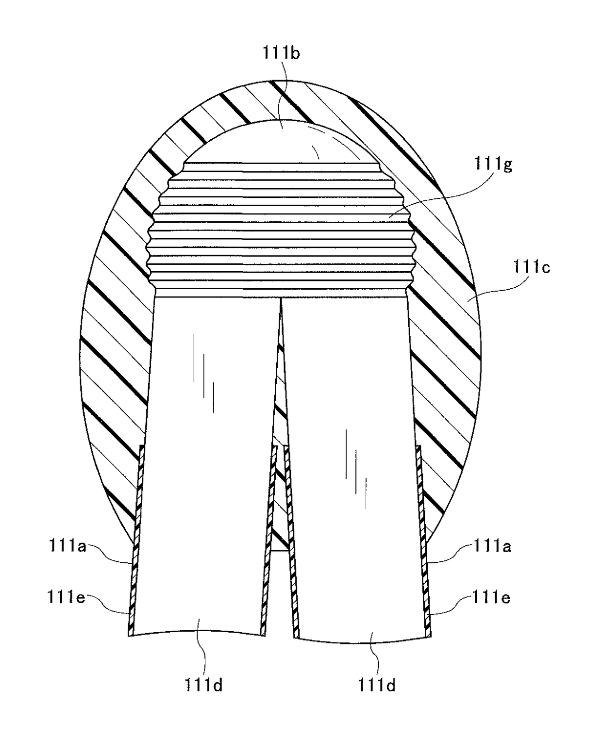
[0083]Specifically, in the present embodiment, as shown in FIG. 10, each of the welds 211b is formed by welding end portions of one pair of the electric conductors 211d of the electric conductor segments 211a. Moreover, each of the welds 211b has the uneven portion 211g formed on the surface thereof.

[0084]As shown in FIG. 12, the uneven portion 211g is formed by cutting at least part of the surface of the weld 211b with a cutting tool CT while rotating the weld 211b.

[0085]More specifically,...

third embodiment

[0089]A rotating electric machine 1 according to a third embodiment has almost the same structure as the rotating electric machine 1 according to the first embodiment. Accordingly, only the differences therebetween will be described hereinafter.

[0090]In the first embodiment, the uneven portions of the welds are formed by pressing the die M against the surfaces of the welds. In comparison, in the present embodiment, each of the electric conductors of the electric conductor segments is constituted of a plurality of electric conductor wires; the uneven portions of the welds are formed by a shield gas flow and a magnetic field created during the welding of end portions of the electric conductors.

[0091]Specifically, in the present embodiment, as shown in FIGS. 13 and 14, each of the electric conductor segments 311a includes an electric conductor 311d and a conductor-insulating member 311e. The electric conductor 311d is constituted of a plurality of electric conductor wires 311h having a...


PUM


Abstract

A rotating electric machine includes a weld formed by welding end portions of a pair of electric conductors for forming a coil and a weld-insulating member that covers, at least, a surface of the weld. The weld has an uneven portion formed on at least part of the surface thereof. The uneven portion is constituted of a plurality of annular recesses and a plurality of annular protrusions. The annular recesses are formed alternately and continuously with the annular protrusions.

Description

CROSS-REFERENCE TO RELATED APPLICATION[0001]This application is based on and claims priority from Japanese Patent Application No. 2015-148301 filed on Jul. 28, 2015, the content of which is hereby incorporated by reference in its entirety into this application.BACKGROUND[0002]1 Technical Field[0003]The present invention relates to rotating electric machines which have welds formed by welding end portions of electric conductors for forming a coil and weld-insulating members that cover, at least, the surfaces of the welds, and to methods of manufacturing the rotating electric machines.[0004]2 Description of Related Art[0005]There are known rotating electric machines which have welds formed by welding end portions of electric conductors for forming a coil and weld-insulating members that cover, at least, the surfaces of the welds.[0006]In the rotating electric machines, there is generally a large temperature difference between when the rotating electric machines are in an operating sta...

Claims


Application Information

Patent Timeline
Patent Type & Authority Patents(United States)
IPC IPC(8): H02K1/00H02K3/12H02K3/32H02K15/00H02K3/38H02K3/04
CPCH02K3/12H02K3/04H02K15/0081H02K3/38H02K15/0037H02K3/32
Inventor ISHIZUKA, ATSUOKANEIWA, HIROSHIKONDOU, KEIJIASAI, HIROMITSU
Owner DENSO CORP
Why Eureka
Try Eureka