Shrink-wrap collar from DRAM deep trenches

a technology of shrink wrap and trench collar, which is applied in the direction of semiconductor electronic devices, electrical equipment, basic electric elements, etc., can solve the problems of affecting the reliability of operation, the reduction of charge storage can rarely be fully compensated, and the operating margin may be severely compromised

Inactive Publication Date: 2000-05-30
SIEMENS MOBILITY INC
View PDF12 Cites 34 Cited by
  • Summary
  • Abstract
  • Description
  • Claims
  • Application Information

AI Technical Summary

Problems solved by technology

However, in any given technology and for any particular design ground rules, such as minimum feature size, there is a trade-off between the minimum size or maximum integration density which can be achieved and the manufacturing yield.
Devices which rely on particular dimensions for their electrical properties, such as capacitors used in dynamic memories (e.g. dynamic random access memories (DRAM's)), however, present additional trade-offs in design.
(Of course, capacitance may be increased by reduction of electrode spacing, consistent with capacitor size reduction in integrated circuits, but reduction in charge storage can seldom be fully compensated as capacitor size is reduced.)
On the other hand, if the capacitance of each cell is reduced to increase the number of cells without corresponding decrease in parasitic capacitance of word and bit lines connected to the memory cells, operating margins may be severely compromised.
Further, as charge storage is reduced, other effects such as charge leakage become more critical to reliable operation.
However, deep trench (or, simply, "trench") capacitors are still subject to charge leakage.
Charge leakage, in particular, is of particular concern since capacitance of individual memory cell capacitors is necessarily small.
Therefore, even slight charge leakage may be sufficient to cause loss or at least compromise of stored data unless the memory refresh period is reduced.
Therefore, full exploitation of potential integration density at the current state of lithographic technology is limited by permissible proximity of trench capacitors which cannot be spaced closer than twice the likely extent of crystal lattice dislocations without comprising isolation between capacitors.
This effect is particularly true of oxides which shrink less than the substrate when cooled, resulting in persistent compressive stresses.
Compressive stresses can also result from a volume increase in films due to inclusions or growth of materials (e.g. grown oxides), which may not be fully avoidable or occur spontaneously during other processes (e.g. impurity diffusion).
While several mechanisms such as recrystallization and chemical reactions are known to cause volume reduction, many are not compatible with devices being fabricated and volume reduction is generally very small and not well-controllable.

Method used


Image

  • Shrink-wrap collar from DRAM deep trenches
  • Shrink-wrap collar from DRAM deep trenches
  • Shrink-wrap collar from DRAM deep trenches

Examples


Embodiment Construction

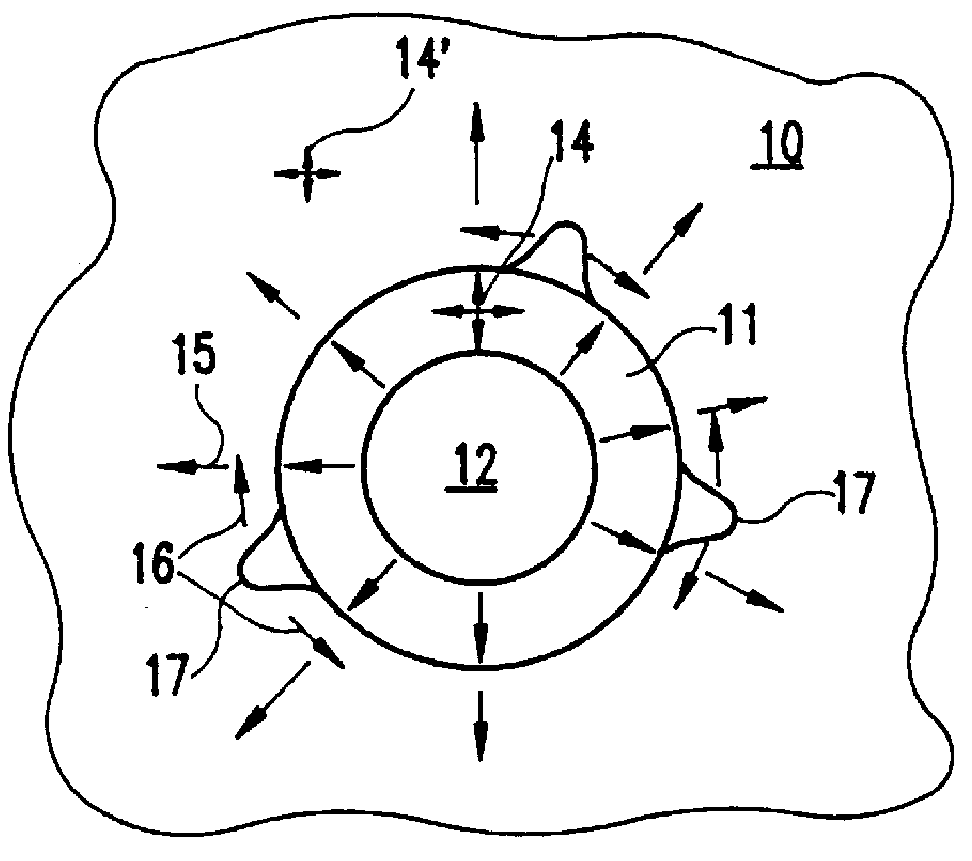
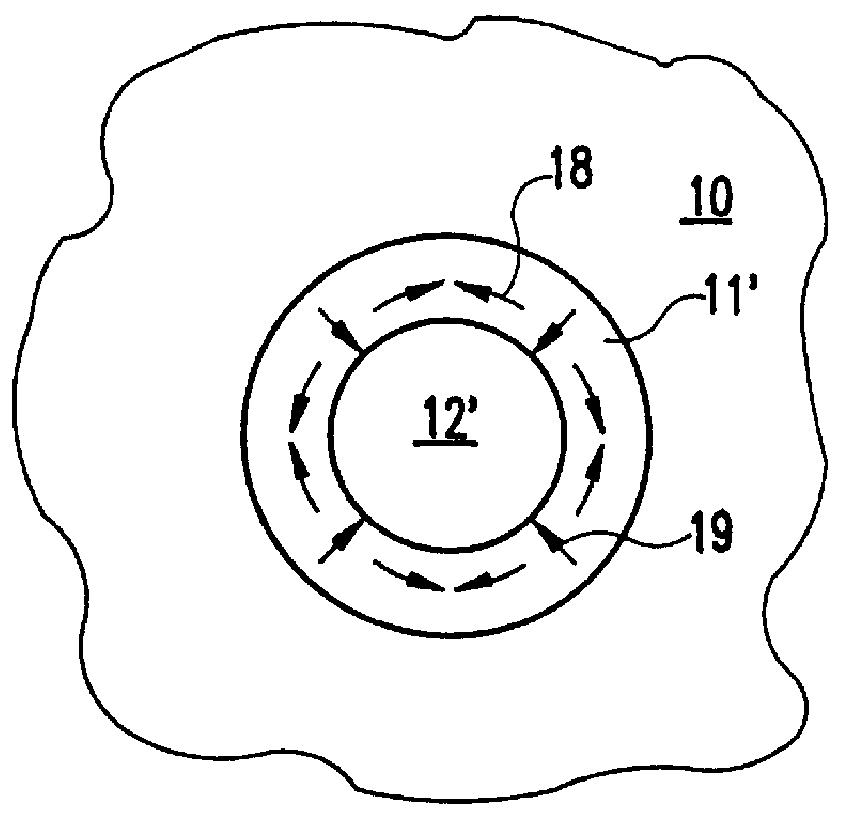
Referring now to the drawings, and more particularly to FIG. 1A, there is shown a plan view of a trench and an oxide capacitor dielectric collar as would be used in a capacitor formed in an integrated circuit device. This Figure is designated as "Related Art" since arrows designating stresses are intended to be indicative of the problem encountered in devices more subject to the formation of crystal lattice dislocations than the present invention and to which the present invention provides a solution. However, it is to be understood that no portion of the structure illustrated in FIG. 1A is to be considered as an admission of prior art as to the present invention. Also, the shape of the trench, in plan view, is relatively arbitrary as a matter of design convenience and unimportant to the practice of the invention; a somewhat elongated oval shape being preferred to the circular form illustrated for reasons not relevant to the practice of the present invention. Further, it is to be un...


PUM

PropertyMeasurementUnit
sizeaaaaaaaaaa
sizeaaaaaaaaaa
volume shrinkageaaaaaaaaaa

Abstract

Crystal lattice dislocations in material surrounding trench capacitors and other trench structures are avoided by alteration of stresses such as decreasing compressive stresses and/or development of persistent tensile forces within material deposited in the trench and thus at the material interface formed by the trench. Such alteration of stresses is achieved by volume reduction of a film deposited in the trench. The material is preferably a hydrogenated nitride of silicon, boron or silicon-carbon alloy which may be reduced in volume by partial or substantially complete dehydrogenation during subsequent heat treatment at temperatures where the film will exhibit substantial creep resistance. The amount of volume reduction can be closely controlled by control of concentration of hydrogen or other gas or volatile material in the film. Further fine adjustment of stresses can be achieved in combination with this mechanism by volume reduction of other materials which may be used, in part, to confine the film through other mechanisms such as annealing.

Description

1. Field of the InventionThe present invention generally relates to the formation of trench structures in semiconductor electronic devices and, more particularly, to the formation of deep trench capacitor structures for integrated circuit memories.2. Description of the Prior ArtThe need for memory structures of increased device density has generally followed similar trends in other integrated circuit devices such as microprocessors in order to provide improvements in speed and function as well as economies of manufacture, so long as manufacturing yields can be maintained. Decreased circuit element size is generally accompanied by decreases in parasitic capacitances and decreased signal propagation time between circuit elements. The increase in number of circuit elements which can be formed on a single chip yields increases in functionality. Likewise, an increase in the number of circuit elements which can be formed on a single chip or wafer yields economies in manufacturing processe...

Claims


Application Information

Patent Timeline
Patent Type & Authority Patents(United States)
IPC IPC(8): H01L21/02H01L21/334H01L21/70H01L21/8242
CPCH01L29/66181H01L27/10861H10B12/038
Inventor GEISS, PETER JOHNLANDIS, HOWARD SMITHNGUYEN, SON VAN
Owner SIEMENS MOBILITY INC
Why Eureka
Try Eureka