Heat dissipation device

a heat dissipation device and heat pipe technology, applied in the direction of indirect heat exchangers, lighting and heating apparatus, etc., can solve the problems that one heat pipe or one vapor chamber attached to electronic elements cannot meet the requirement of heat dissipation, and the internal space of electronic mobile devices for disposing electronic elements is also limited, so as to improve heat dissipation efficiency and enhance heat dissipation effect, the effect of rapid diffusion of hea

Active Publication Date: 2018-09-18
ASIA VITAL COMPONENTS SHENZHEN CO LTD
View PDF19 Cites 3 Cited by
  • Summary
  • Abstract
  • Description
  • Claims
  • Application Information

AI Technical Summary

Benefits of technology

[0008]Another object of the present invention is to provide a heat dissipation device that can have a condensed liquid working fluid flow back with the help of a capillary force and gravity to achieve improved heat transfer efficiency since a pipe wick structure of the pipe is connected to the first and the second wick structure of the first and the second housing.
[0009]A further object of the present invention is to provide a heat dissipation device that can quickly diffuse heat with assembled a first and a second heat radiation fin assembly, so as to enhance heat transfer effect.
[0010]To achieve the above and other objects, the heat dissipation device provided according to the present invention includes a first and a second housing, at least one pipe, and a working fluid. The first housing internally defines a first chamber, in which a first wick structure is formed, and has at least one first opening communicated with the first chamber, whereas the second housing internally defines a second chamber, in which a second wick structure is formed, and has at least one second opening communicated with the second chamber. The pipe has a pipe body, and a first and second extended portion formed on the two opposite end thereof. The first and the second extended portion has a first and a second open end, and a first and a second through opening, and is inserted into and connected to the first and the second chamber via the first and the second opening of the first and the second housing respectively. The pipe body internally defines a pipe chamber, in which a pipe wick structure is formed. The working fluid is provided in the first and the second, and the pipe chamber. Furthermore, since there is no interface thermal resistance at junctures between the first and the second housing, and the pipe, the heat transfer efficiency of the heat dissipation device can be largely enhanced.

Problems solved by technology

The currently available electronic mobile devices have become extremely thin and light.
Due to the improved computation performance and the largely reduced overall thickness, an internal space of the electronic mobile devices for disposing electronic elements is also limited.
Currently, only one heat pipe or one vapor chamber attached to electronic elements cannot meet the requirement of heat dissipation.

Method used


Image

  • Heat dissipation device
  • Heat dissipation device
  • Heat dissipation device

Examples


Embodiment Construction

[0028]The present invention will now be described with some preferred embodiments thereof and by referring to the accompanying drawings. For the purpose of easy to understand, elements that are the same in the preferred embodiments are denoted by the same reference numerals.

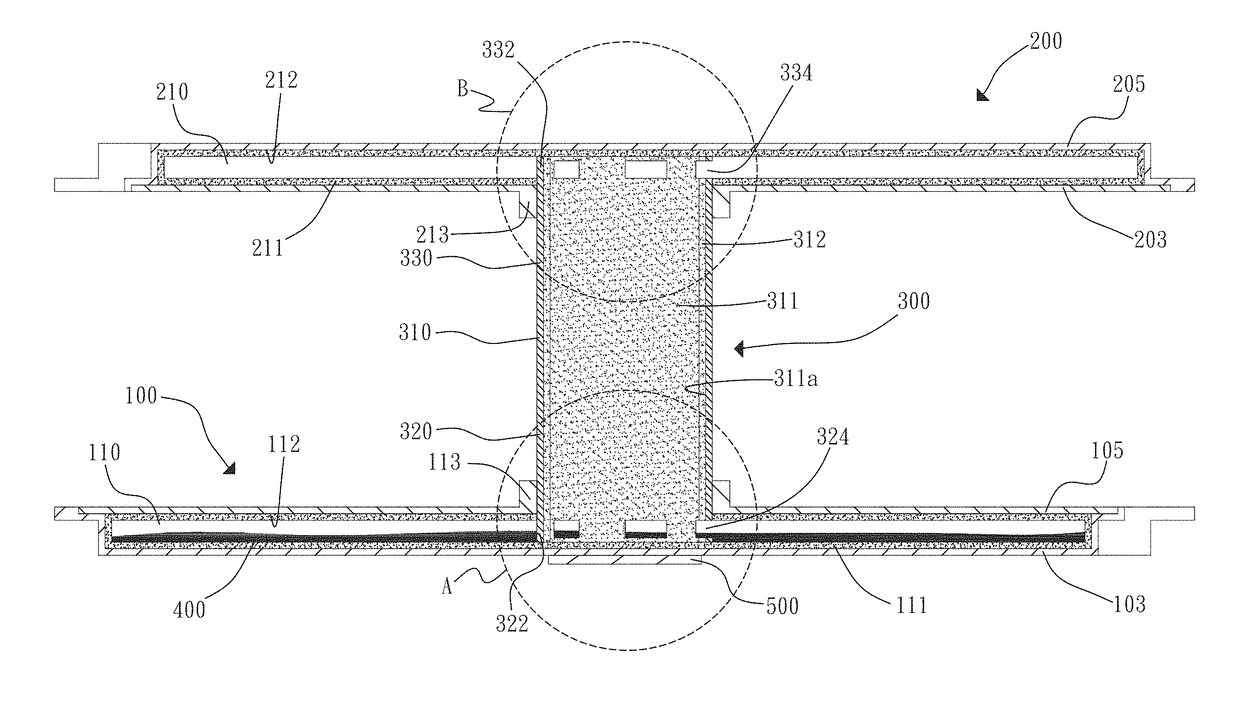
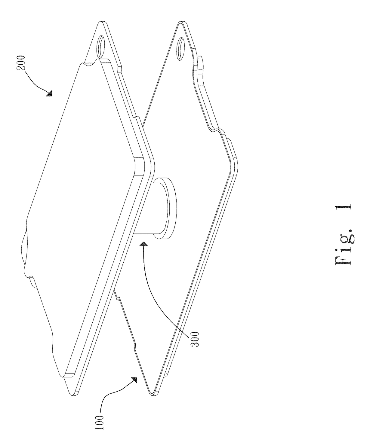
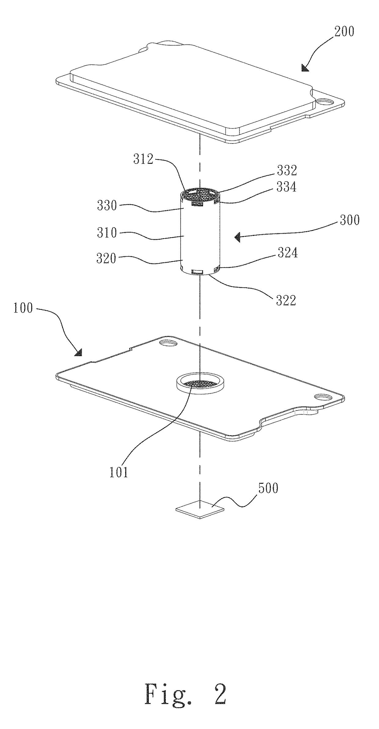
[0029]Please refer to FIGS. 1, 2, 2a, which are assembled and exploded perspective views, respectively, of a heat dissipation device according to a first embodiment of the present invention, and FIGS. 3 to 5, which are assembled sectional and two partially enlarged views, respectively, of the heat dissipation device according to the first embodiment of the present invention. As shown, the heat dissipation device includes a first and a second housing 100, 200, at least one pipe 300, and a working fluid 400.

[0030]In this illustrative first embodiment, the first and the second housing 100, 200 can be, for example but not limited to, a vapor chamber or other materials that can provide the same effect in practical imp...


PUM


Abstract

A heat dissipation device includes a first and a second housing, at least one pipe, and a working fluid. The first and the second housing internally respectively defines a first and a second chamber, in which a first and a second wick structure is respectively formed, and has at least one first and second opening communicated with the first and the second chamber respectively. The pipe has a pipe body, and a first and second extended portion, which respectively has a first and a second open end, and a first and a second through opening, and is inserted into and connected to the first and the second chamber via the first and the second opening respectively. The pipe internally defines a pipe chamber, in which a pipe wick structure is formed. The working fluid is provided in the first and the second, and the pipe chamber.

Description

FIELD OF THE INVENTION[0001]The present invention relates to a heat dissipation device, and more specifically, to a heat dissipation device that can have no interface thermal resistance at junctures between the first and the second housing, and the pipe, have enhanced heat transfer efficiency, have increased vapor / liquid circulation effect, be manufactured at lower costs, and remove heat more quickly.BACKGROUND OF THE INVENTION[0002]The currently available electronic mobile devices have become extremely thin and light. Apart from being thin and light, the new-generation electronic mobile devices have also largely improved computation performance. Due to the improved computation performance and the largely reduced overall thickness, an internal space of the electronic mobile devices for disposing electronic elements is also limited. The higher the computation performance is, the more amount of heat the electronic elements produce during operation. Therefore, vapor chambers and heat p...

Claims


Application Information

Patent Timeline
Patent Type & Authority Patents(United States)
IPC IPC(8): F28D15/02F28D15/04F28D21/00
CPCF28D15/0233F28D15/0266F28D15/046F28D2021/0028
Inventor LAN, WEN-JI
Owner ASIA VITAL COMPONENTS SHENZHEN CO LTD
Why Eureka
Try Eureka