Sensor integrated metal dielectric filters for solar-blind silicon ultraviolet detectors
What is AI technical title?
AI technical title is built by PatSnap AI team. It summarizes the technical point description of the patent document.
a technology of ultraviolet detectors and dielectric filters, applied in the field of detector filters, can solve the problems of solar rejection, reduced signal-to-noise ratio, and limited device performance, and achieve the effects of improving out-of-band rejection, improving the admittance matching of the structure, and increasing peak transmission
Active Publication Date: 2018-09-18
CALIFORNIA INST OF TECH
View PDF18 Cites 0 Cited by
Summary
Abstract
Description
Claims
Application Information
AI Technical Summary
This helps you quickly interpret patents by identifying the three key elements:
Problems solved by technology
Method used
Benefits of technology
Benefits of technology
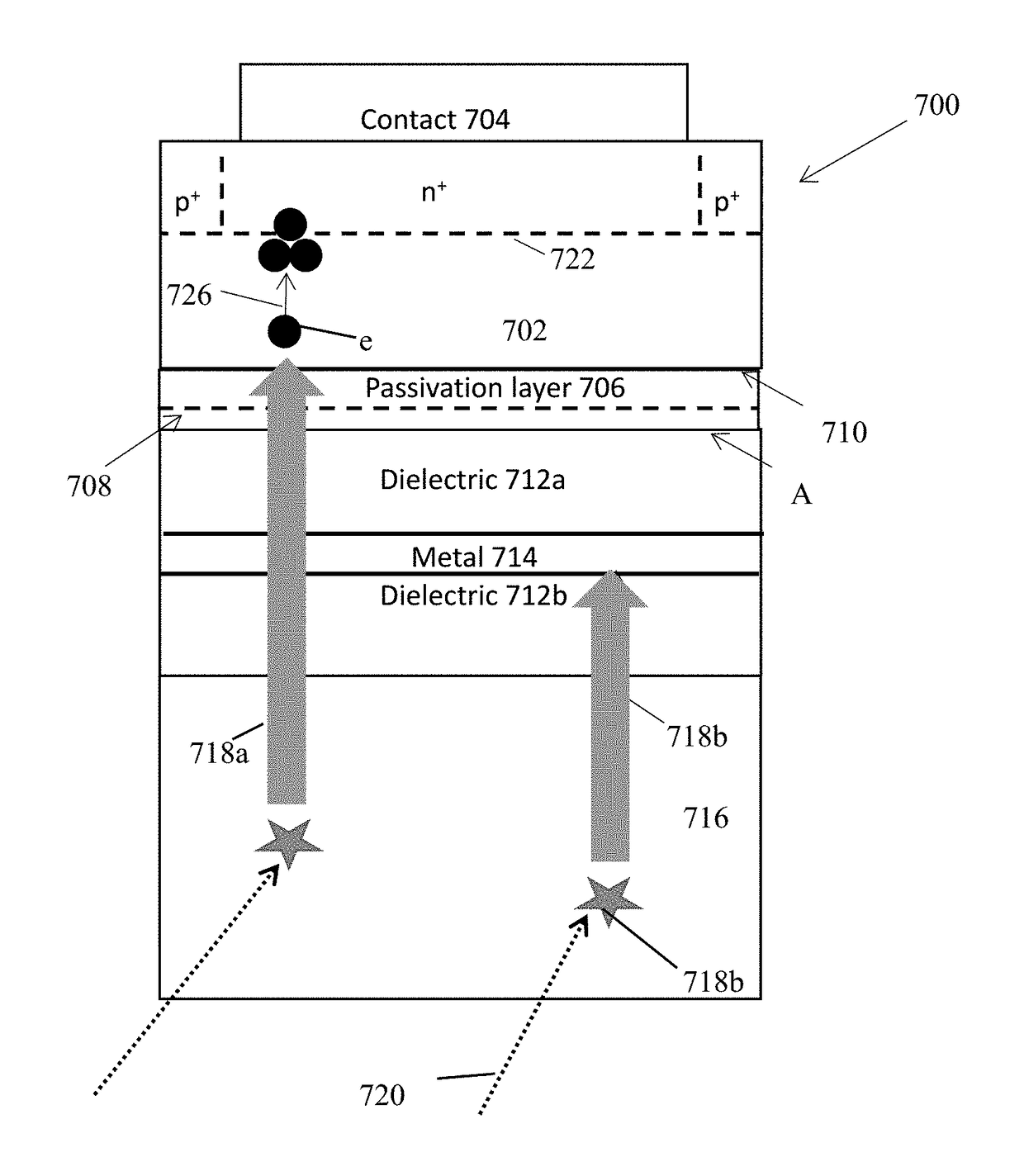
[0009]One or more embodiments of the invention disclose the fabrication of metal-dielectric thin film stacks deposited directly onto semiconductor (e.g., silicon) substrates for use as ultraviolet bandpass filters. Integration of these filters onto semiconductor (e.g., silicon) improves the admittance matching of the structure when compared to similar designs fabricated on transparent substrates, leading to higher peak transmission or improved out-of-band rejection if used with a semiconductor based (e.g., Si-based) sensor platform.
[0013]destructively phase-match reflection of the ultraviolet radiation off of the reflective regions so as to increase transmission of the ultraviolet radiation through the filter to the semiconductor photodetector, and
[0014]increase reflection of the out-of-band electromagnetic radiation off of the reflective regions and away from the semiconductor photodetector.
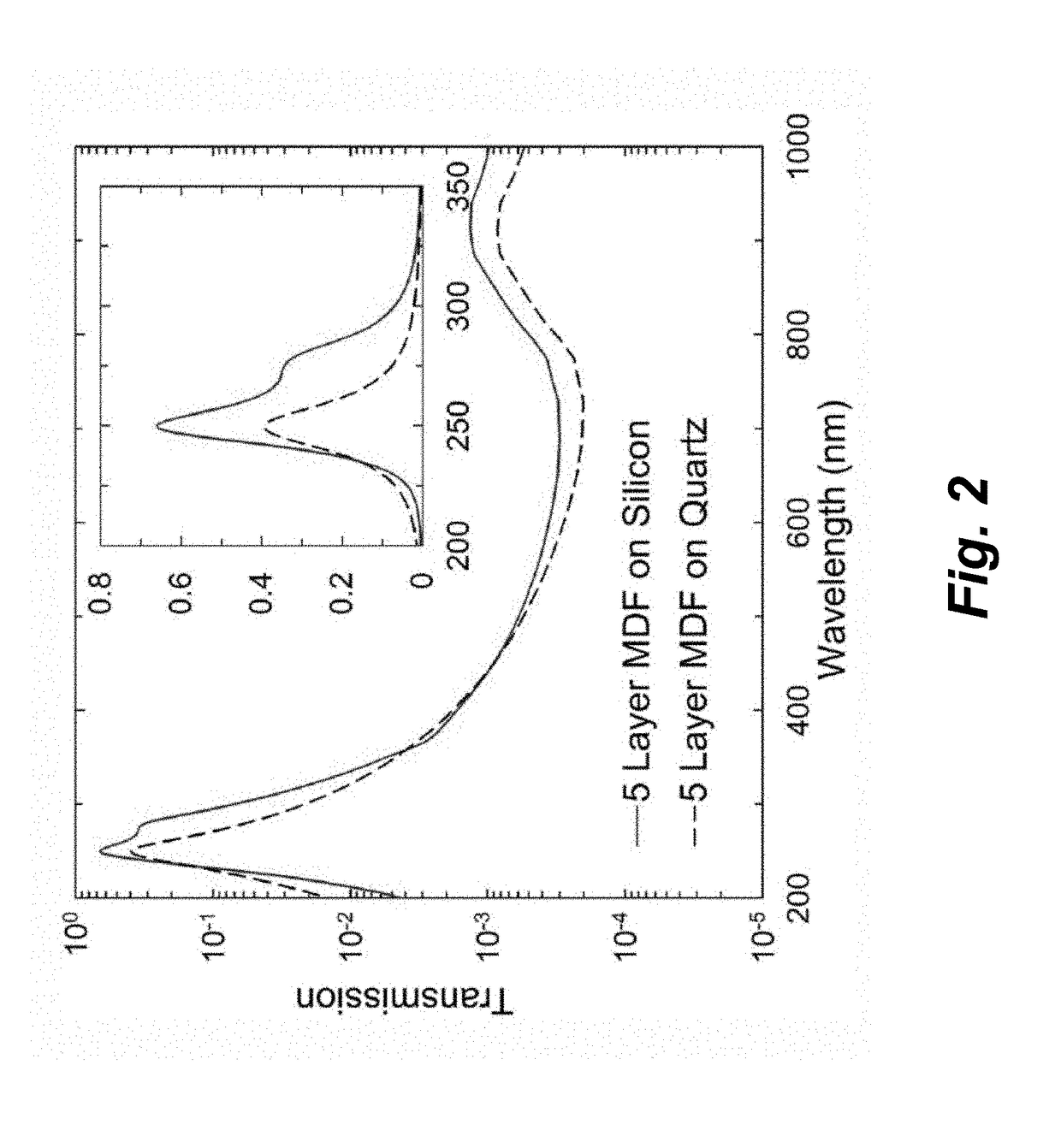
[0017]for example, higher transmission for the ultraviolet radiation, and increased reflectivity of the out-of-band electromagnetic radiation, as compared to a filter comprising each of the metal layers separating two of the dielectric layers and deposited on a quartz substrate; and / or
Problems solved by technology
One major challenge facing UV detection is visible or solar rejection, as UV photons in bands of interest are often greatly outnumbered by visible photons, effectively reducing the signal-to-noise ratio.
These materials are inherently insensitive to lower-energy photons, but device performance is typically limited by material quality issues that degrade quantum efficiency in the ultraviolet.
Method used
Image
Click on the blue label to locate the original text in one second.
Reading with bidirectional positioning of images and text.
Examples
Embodiment Construction
[0039]In the following description of the preferred embodiment, reference is made to the accompanying drawings which form a part hereof, and in which is shown by way of illustration a specific embodiment in which the invention may be practiced. It is to be understood that other embodiments may be utilized and structural changes may be made without departing from the scope of the present invention.
[0040]Technical Description
[0041]One or more embodiments of the present invention show that the concept of metal-dielectric bandpass filters can be extended for use directly on a semiconductor (e.g., silicon (Si)) photodetector, and can achieve superior transmission / rejection performance when compared to similar structures fabricated on transparent substrates as stand-alone filter elements. In this way, the concept of visible band rejection can be extended to a semiconductor (e.g., silicon) sensor platform for use in a narrow- to medium-band UV imager, or implemented with a stepped or wedge...
PUM
Abstract
A filter for electromagnetic radiation including one or more dielectric spacer regions and one or more reflective regions integrated on a semiconductor substrate, the semiconductor substrate including a semiconductor photodetector, such that the filter transmits ultraviolet radiation to the semiconductor photodetector, the ultraviolet radiation having a range of wavelengths, and the filter suppresses transmission of electromagnetic radiation, having wavelengths outside the range of wavelengths, to the semiconductor photodetector.
Description
CROSS REFERENCE TO RELATED APPLICATIONS[0001]This application claims the benefit under 35 U.S.C. Section 119(e) of commonly-assigned U.S. Provisional Patent Application Ser. No. 62 / 113,658, filed on Feb. 9, 2015, by Michael E. Hoenk, John J. Hennessy, Shouleh Nikzad, and April D. Jewell, entitled “SENSOR INTEGRATED METAL DIELECTRIC FILTERS FOR SOLAR-BLIND SILICON ULTRAVIOLET DETECTORS,” which application is incorporated by reference herein.[0002]This application is related to U.S. patent application Ser. No. 14 / 670,365 filed on Mar. 26, 2015, by Michael E. Hoenk, John Hennessy, and David Hitlin, entitled “SUBNANOSECOND SCINTILLATION DETECTOR,” which application claims the benefit under 35 U.S.C. Section 119(e) of U.S. Provisional Patent Application Ser. No. 61 / 970,779, filed on Mar. 26, 2014, by Michael Hoenk and David Hitlin, entitled “SUBNANOSECOND SCINTILLATION DETECTOR,” client reference number CIT-6868-P, which applications are incorporated by reference herein.STATEMENT REGARDI...
Claims
Application Information
Patent Timeline
Application Date:The date an application was filed.
Publication Date:The date a patent or application was officially published.
First Publication Date:The earliest publication date of a patent with the same application number.
Issue Date:Publication date of the patent grant document.
PCT Entry Date:The Entry date of PCT National Phase.
Estimated Expiry Date:The statutory expiry date of a patent right according to the Patent Law, and it is the longest term of protection that the patent right can achieve without the termination of the patent right due to other reasons(Term extension factor has been taken into account ).
Invalid Date:Actual expiry date is based on effective date or publication date of legal transaction data of invalid patent.

