
Noise canceler

a technology of noise canceling and noise canceling, which is applied in the field of noise canceling, can solve the problems of difficult to remove interference signals by filters or the like, interfere with the band of a cell phone, and deterioration of the communication environment, so as to improve avoid the effect of deterioration in the communication quality of the desired signal

Active Publication Date: 2018-09-18
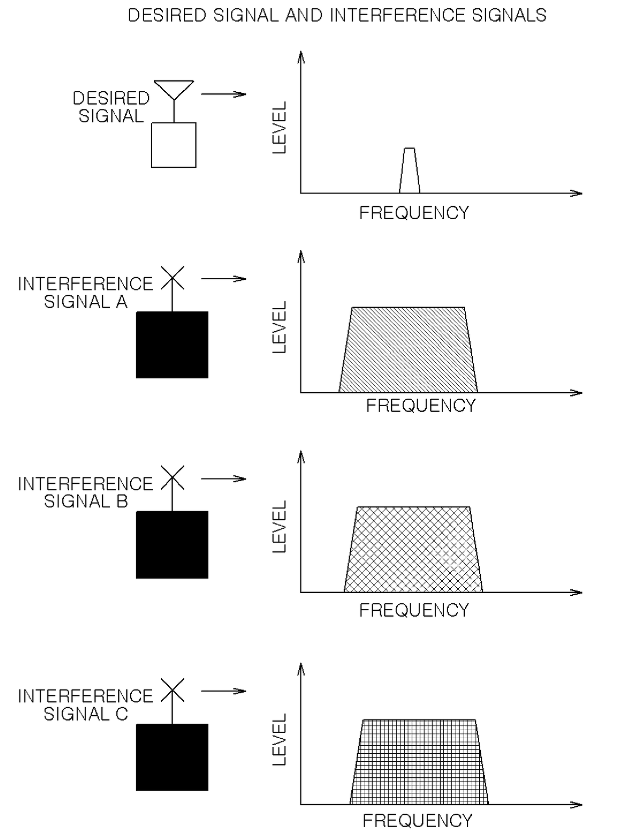
KOKUSA ELECTRIC CO LTD
View PDF9 Cites 0 Cited by
  • Summary
  • Abstract
  • Description
  • Claims
  • Application Information

AI Technical Summary

Benefits of technology

The noise canceler effectively improves communication quality by accurately removing interference signals from other systems, even when signals other than the target interference are present, thereby maintaining the quality of desired signals.

Problems solved by technology

In a conventional wireless communication system, a communication environment may deteriorate because a signal of another system becomes an interference signal for a desired signal.
If radio waves leak from the reception equipment at that time, a band of a cell phone is interfered.
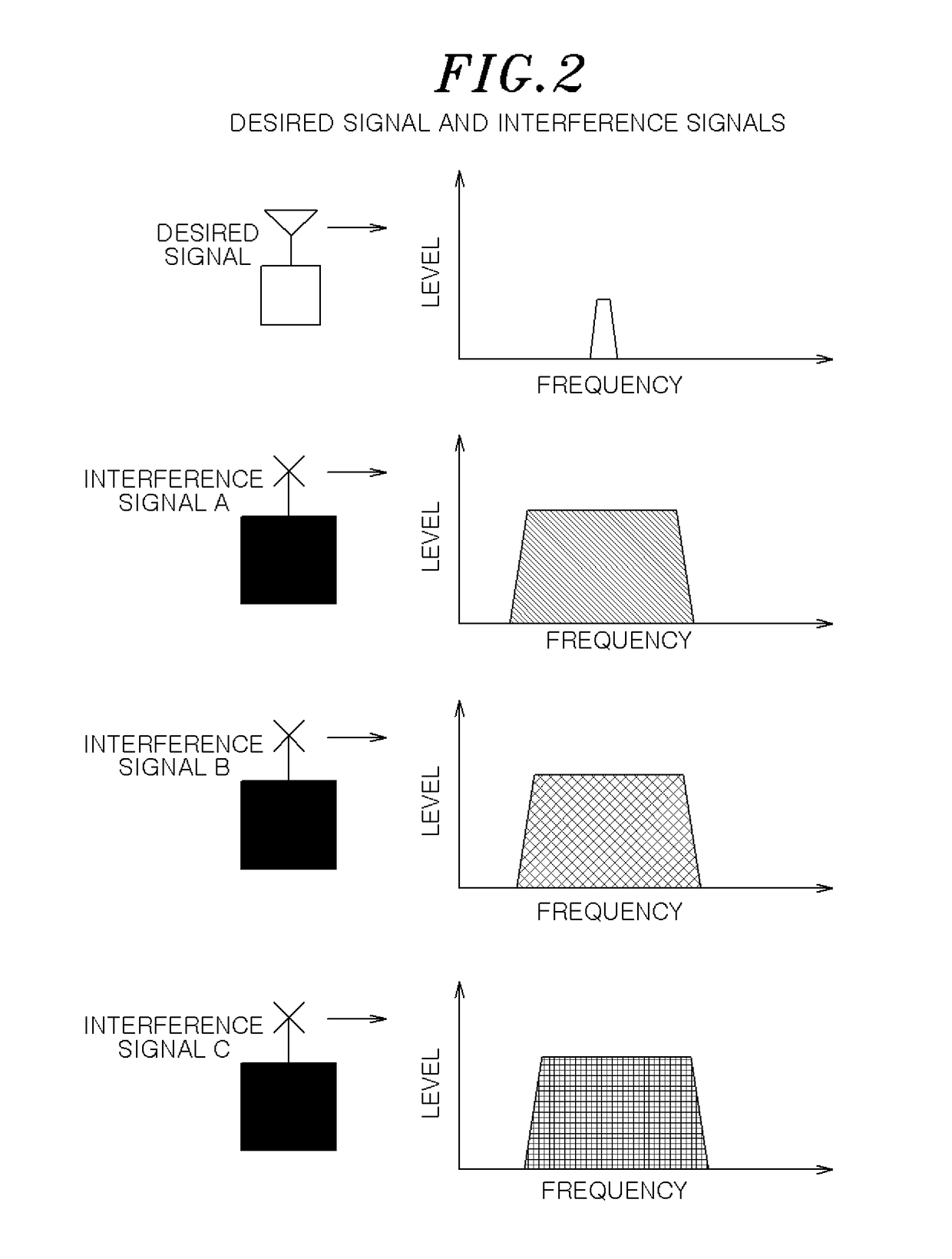
A signal band as an interference signal for a band of a cell phone as a desired signal is wider than the band of the cell phone, it is difficult to remove the interference signal by a filter or the like.
However, when it is not possible to prepare a replica of the interference signal, it is difficult to remove only the interference signal.
However, in the conventional wireless communication system for a cell phone, the interference signal from another system such as the broadcasting satellite reception equipment having a BS antenna may not be removed, which results in deterioration of a communication quality of a cell phone as a desired signal.

Method used


Image

  • Noise canceler
  • Noise canceler
  • Noise canceler

Examples


application example

[0205]( Directivity of Sub-Antenna)

[0206]Hereinafter, an application example of the present embodiment will be described.

[0207]The noise cancelers except the third noise canceler have sub-antennas. If the sub-antennas have directivity toward a specific interference source, the interference signal can be received with high accuracy. Accordingly, the cancel effect can be improved.

[0208](Effects of Embodiments)

[0209]In accordance with the embodiments of the present invention, the information on the interference signal is acquired by performing cross-correlation processing on a plurality of received interference signals; the plurality of received interference signals is synthesized based on the information and outputted; the information on the interference signal included in the received signals is acquired by performing correlation processing on the received signals and the synthesized interference signal; the interference signal replica is generated based on the information; and the i...


PUM


Abstract

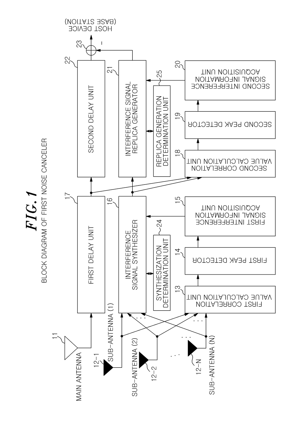
In a noise canceler, interference signals received by sub-antennas 12 are cross-correlated by a first correlation-value calculation unit and the peaks of the interference signals are detected by a first peak detector. Interference signal information is acquired by a first-interference-signal information acquisition unit and the interference signals are synthesized by an interference signal synthesizer. A signal received by a main antenna and the synthesized interference signal are correlated by a second correlation-value calculation unit and the peak of the synthesized interference signal is detected by a second peak detector. The interference signal information is acquired by a second interference-signal-information acquisition unit and an interference signal replica is generated by an interference signal replica generator. The interference signal replica is subtracted by an interference signal removal unit from the signal received by the main antenna.

Description

FIELD OF THE INVENTION[0001]The present invention relates to a noise canceler in a wireless communication system; and, more particularly, to a noise canceler capable of removing interference signals from other systems.BACKGROUND OF THE INVENTION[0002]In a conventional wireless communication system, a communication environment may deteriorate because a signal of another system becomes an interference signal for a desired signal.[0003]For example, in broadcasting satellite reception equipment having a BS (broadcasting satellite) antenna installed in each house, frequency conversion is often used to process a received signal. If radio waves leak from the reception equipment at that time, a band of a cell phone is interfered.[0004]A signal band as an interference signal for a band of a cell phone as a desired signal is wider than the band of the cell phone, it is difficult to remove the interference signal by a filter or the like. A known interference signal can be removed by generating...

Claims


Application Information

Patent Timeline
Patent Type & Authority Patents(United States)
IPC IPC(8): H04B1/10H04L25/03
CPCH04B1/10H04B1/1027H04L25/0328H04B1/123H04B1/7107
Inventor KUSHIOKA, YOICHITAKASHIMA, MITSUHIRO
Owner KOKUSA ELECTRIC CO LTD
Learn More