Heating body, resonation device, electronic apparatus, and moving object

a resonant device and electronic equipment technology, applied in the direction of ohmic-resistance heating, semiconductor devices, impedence networks, etc., can solve problems such as wiring disconnections, and achieve the effect of reducing the possibility of disconnection caused by electromigration and high reliability

Active Publication Date: 2018-09-25
SEIKO EPSON CORP
View PDF25 Cites 0 Cited by
  • Summary
  • Abstract
  • Description
  • Claims
  • Application Information

AI Technical Summary

Benefits of technology

[0006]An advantage of some aspects of the invention is to provide a heating body capable of reducing possibility of disconnection caused by electromigration, a resonation device using the heating body, and an electronic apparatus and a moving object using the heating body or the resonation device.
[0009]In the heating body according to this application example, since the input unit that inputs the current to the heating unit formed on the semiconductor substrate is arranged such that the current flows between the front surface and the rear surface, the thickness of the input unit is the distance that the current flows and the area of the input unit is the cross-sectional area that the current flows. Accordingly, it is possible to decrease the density of the current flowing into the input unit and to reduce possibility of disconnection caused by electromigration.Application Example 2
[0011]In the heating body according to this application example, since the first electrode and the second electrode that input and output the current with respect to the diffusion resistance layer formed on the semiconductor substrate are arranged such that the current flows between the surfaces respectively in contact with the diffusion resistance layers and the rear surfaces thereof, the thicknesses of the first electrode and the second electrode are the distance that the current flows and the areas of the first electrode and the second electrode are the cross-sectional area that the current flows. Accordingly, it is possible to decrease the density of the current flowing into the first electrode and the second electrode and to reduce possibility of disconnection caused by electromigration.Application Example 3
[0013]In the heating body according to this application example, even when aluminum or alloys containing aluminum as a main component having low resistance against electromigration are used as the first electrode and the second electrode, the density of the current flowing into the first electrode and the second electrode can be decreased, and the possibility of disconnection caused by electromigration can be reduced. Further, since aluminum and alloys containing aluminum as a main component are low in cost and have excellent processability, the cost for producing the heating body can be decreased and the first electrode and the second electrode can be easily formed to have desired shapes.Application Example 4
[0027]In the electronic apparatus and the moving object according to these application examples, since the heating body in which the possibility of disconnection caused by electromigration is decreased or the resonation device including the resonator element heated using the heating body is included, it is possible to realize an electronic apparatus and a moving object with high reliability.

Problems solved by technology

However, in the OCXO disclosed in JP-A-2010-213280, the configuration in which the quartz crystal resonator element is arranged on the integrated circuit including the heating body is described, but a metal used for a wiring may cause electromigration so that the wiring is disconnected depending on the configuration of the wiring for supplying power to the heating body because the power to be supplied to the heating body is large in general.
In addition, in JP-A-2009-123354, a wiring that connects a heating body and a lead wiring that supplies power to the planar heating body is provided, but, for example, when a long wiring is used in a direction along the surface between the lead wiring and the heating body in a case where large power is supplied to the heating body, a metal used for the wiring may cause electromigration so that the wiring is disconnected.

Method used


Image

  • Heating body, resonation device, electronic apparatus, and moving object
  • Heating body, resonation device, electronic apparatus, and moving object
  • Heating body, resonation device, electronic apparatus, and moving object

Examples


first embodiment

1-1. First Embodiment

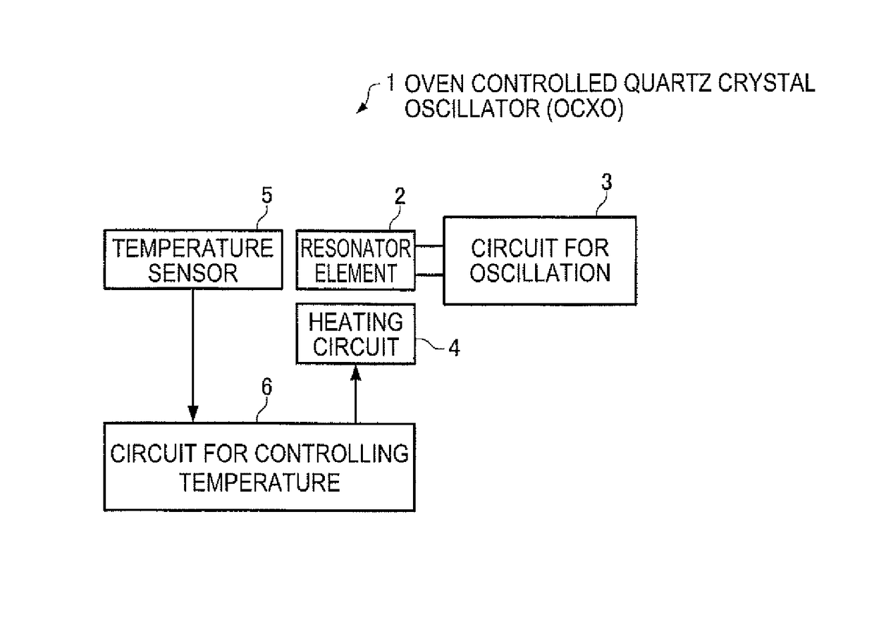
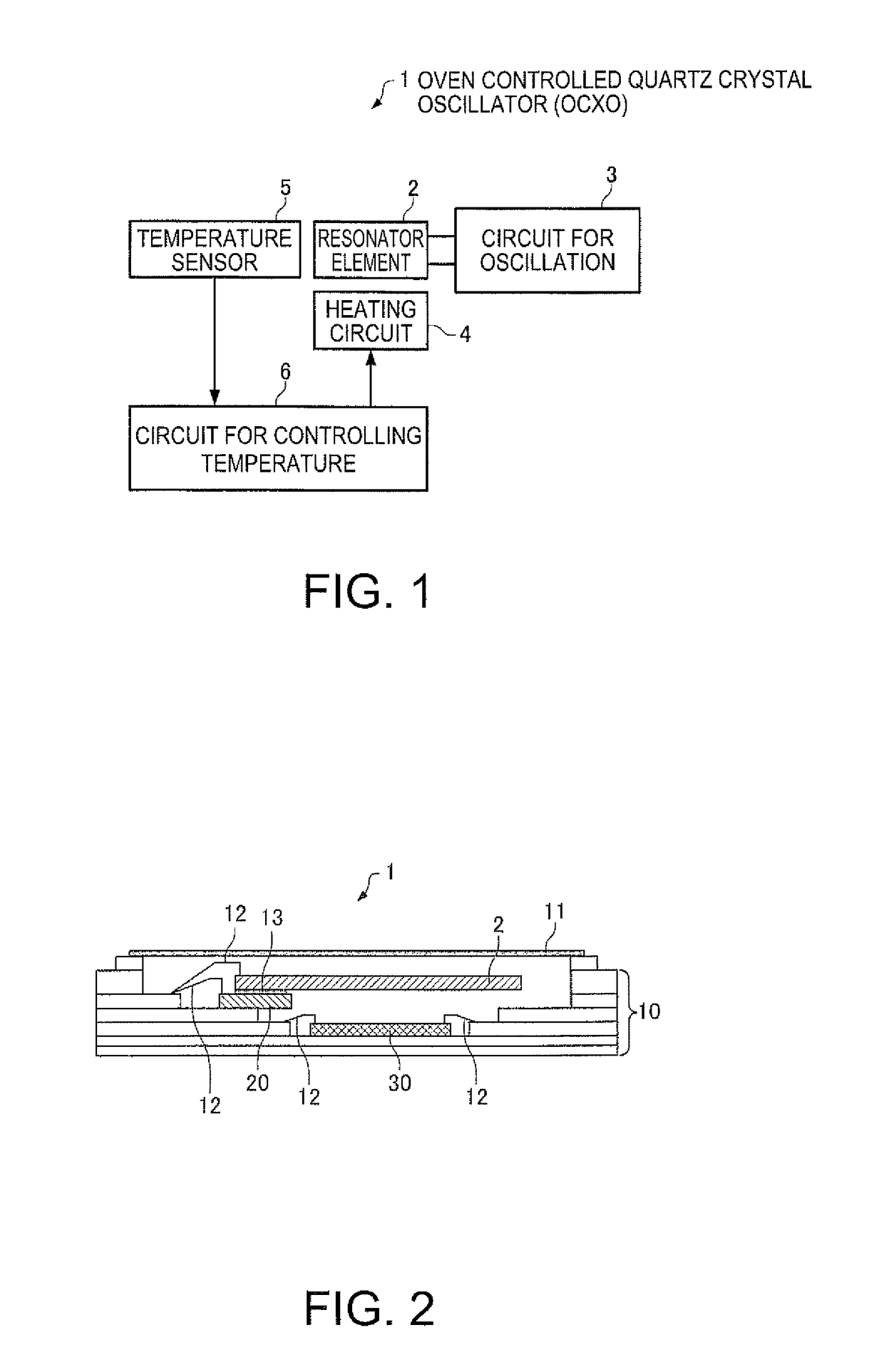
[0049]FIG. 1 is a functional block diagram of an oven controlled quartz crystal oscillator (OCXO) which is an example of a resonation device according to the present embodiment. As illustrated in FIG. 1, the oven controlled quartz crystal oscillator (OCXO) 1 of the present embodiment includes a resonator element 2, a circuit 3 for oscillation, a heating circuit 4, a temperature sensor 5, and a circuit 6 for controlling the temperature. Further, some of these elements of the oven controlled quartz crystal oscillator (OCXO) 1 of the present embodiment may be omitted or changed, and alternatively other elements may be added to the OCXO 1.

[0050]In the present embodiment, the resonator element 2 is a resonator element (quartz crystal resonator) using a quartz crystal as a substrate material, and, for example, a quartz crystal resonator of an AT cut or an SC cut is used for the resonator element 2. However, the resonator element 2 may be a surface acoustic wave (SAW) ...

second embodiment

1-2. Second Embodiment

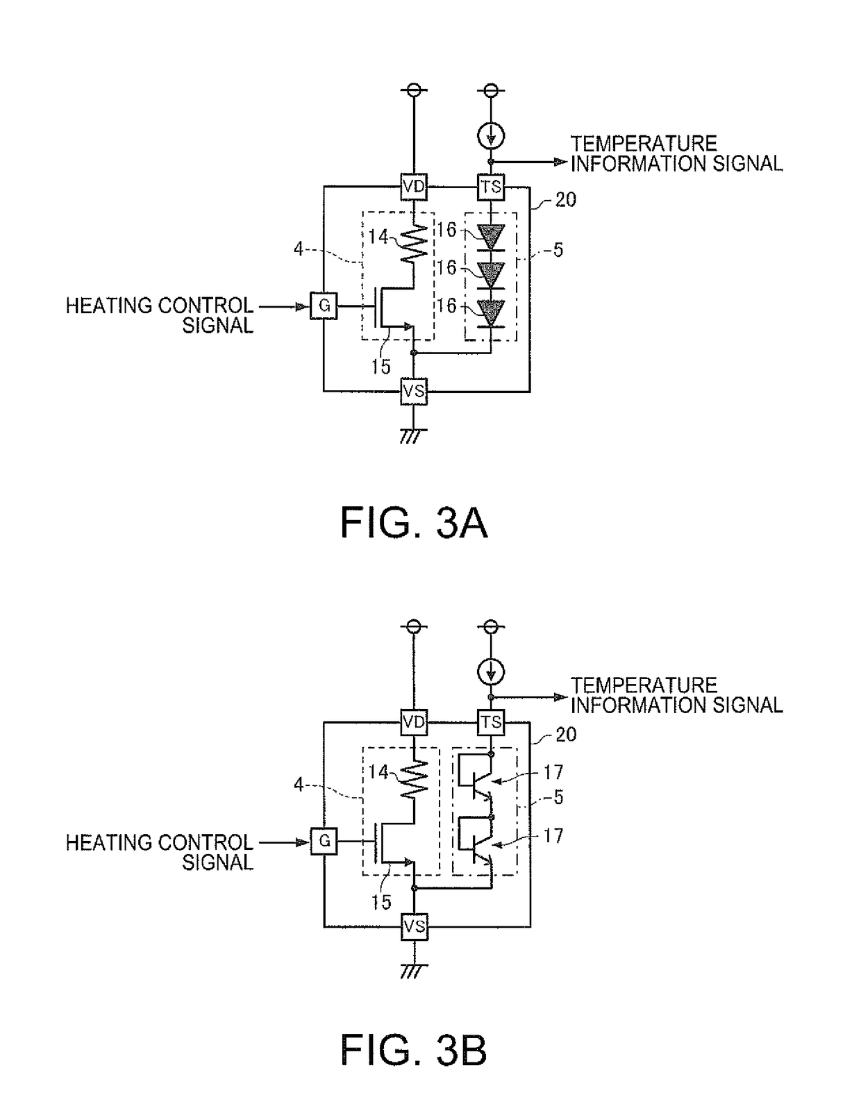
[0101]In the oven controlled quartz crystal oscillator (OCXO) of the first embodiment, since the resistance value of the resistor 14 formed of the diffusion layer 22 is extremely high in some cases, a resistor 14 is realized by a diffusion resistance layer which is configured of a diffusion layer and a conductive layer and whose resistivity is decreased in an oven controlled quartz crystal oscillator (OCXO) of the second embodiment.

[0102]Since a layout pattern of an IC 20 for heating in the oven controlled quartz crystal oscillator (OCXO) of the second embodiment is the same as that of FIG. 4, the illustration is omitted. FIG. 9 is a side view of a rectangular area A of FIG. 4 when seen from a direction of an arrow B in the oven controlled quartz crystal oscillator (OCXO) according to the second embodiment. In FIG. 9, the illustration of MOS transistors arranged on the arrangement area of the MOS transistors of FIG. 4 is omitted.

[0103]As illustrated in FIG. 9, ...

third embodiment

1-3. Third Embodiment

[0107]In the oven controlled quartz crystal oscillator (OCXO) of the first embodiment, the slit 23a is formed so as to intersect the virtual straight line connecting the pads 26a and 26b and the slit 23b is formed so as to intersect the virtual straight line connecting the pads 26i and 26h. Whereas, in an oven controlled quartz crystal oscillator (OCXO) of a third embodiment, two MOS transistors in an OFF state are arranged in place of the slits 23a and 23b and the current flows into the diffusion layer 22 so as to bypass the MOS transistors.

[0108]Since a layout pattern of an IC 20 for heating in the oven controlled quartz crystal oscillator (OCXO) of the third embodiment is the same as that of FIG. 4 except that two MOS transistors are provided in place of the slits 23a and 23b, the illustration is omitted. FIG. 10 is an enlarged view of an area corresponding to the rectangular area A of FIG. 4 in the oven controlled quartz crystal oscillator (OCXO) according t...


PUM


Abstract

An IC for heating includes a semiconductor substrate on which a diffusion layer is formed; a first pad and a first via that apply a power voltage to the diffusion layer; and a second pad and a second via that apply a ground voltage to the diffusion layer. The vias overlap with an area on which the diffusion layer is formed in a plan view, the first pad overlaps with the first via in a plan view, and the second pad overlaps with the second via in a plan view. The current flowing through the first pad and the first via, the second pad and the second via, and the diffusion layer flows between an upper surface of the first pad and a lower surface of the first via, and a lower surface of the second via and an upper surface of the second pad.

Description

BACKGROUND[0001]1. Technical Field[0002]The present invention relates to a heating body, a resonation device, an electronic apparatus, and a moving object, for example, an oven controlled quartz crystal oscillator.[0003]2. Related Art[0004]A quartz crystal oscillator used for reference frequency signal sources of communication equipment or a measuring instrument is required to have a stabilized output frequency with high precision with respect to a change in temperature. In general, an oven controlled quartz crystal oscillator (OCXO) is known as an oscillator capable of obtaining an extremely high frequency stability degree among quartz crystal oscillators. The OCXO is an oscillator that accommodates a quartz crystal resonator in a thermostatic oven whose temperature is controlled to be constant, and JP-A-2010-213280 discloses an OCXO in which a quartz crystal resonator element is arranged on an integrated circuit including a heating body and which is arranged in a package together ...

Claims


Application Information

Patent Timeline
Patent Type & Authority Patents(United States)
IPC IPC(8): H03H9/08H03H9/05H05B3/26
CPCH03H9/08H03H9/0547H05B3/265H01L2224/32145H01L2224/32225H01L2224/48227H01L2224/73265H01L2924/00
Inventor HAYASHI, KENJIFUKUZAWA, AKIHIRO
Owner SEIKO EPSON CORP
Why Eureka
Try Eureka