Automotive construction machine and method for displaying the surroundings of an automotive construction machine

a construction machine and automobile technology, applied in the field of automobile construction machines, can solve the problems of limited view of the operator's surroundings, limited view of the machine operator's front or rear, and limited view of the machine operator's surroundings, so as to achieve the effect of improving the operator's convenience and high degree of operation convenien

Active Publication Date: 2018-10-02
WIRTGEN GMBH
View PDF22 Cites 3 Cited by
  • Summary
  • Abstract
  • Description
  • Claims
  • Application Information

AI Technical Summary

Benefits of technology

[0015]The object of the invention is to provide an automotive construction machine with a transport device extending in the longitudinal direction of the construction machine forward or rearward beyond the machine frame to convey removed material, in particular a road milling machine or surface miner, which provides the machine operator with a high degree of operating convenience. A further object of the invention is to specify a method for improving the operating convenience.
[0022]The transport device preferably has a jib, on which a conveyor belt is arranged, the at least one camera arranged on the transport device being arranged on the lower side of the jib. The at least one camera can basically be arranged on a fastening point over the entire length of the jib. However, the camera should be located above the ground but not located above the loading area of the transport vehicle during the loading process of the construction machine. The at least one camera may be arranged at different viewing angles in relation to the machine frame and therefore in relation to the ground surface. It is advantageous if the camera is as far removed a possible from the front side of the construction machine so that the image region recorded by the camera is as large as possible. In this case, it is also advantageous for the height of the camera to increase in relation to the ground surface with the increasing distance of the camera from the front side of the construction machine, as the transport device is inclined upwardly in the working direction.
[0023]One embodiment provides that the camera system has a camera arranged on the lower side of the jib of the transport device, the camera axis running in the longitudinal direction of the jib, while an alternative embodiment provides two cameras arranged on the lower side of the jib, the camera axes of which run in a sloping manner with respect to the longitudinal direction of the jib. In this case, the viewing direction of the one camera is directed in the direction of the one side of the machine frame and the viewing direction of the other camera is directed in the direction of the other side of the machine frame when the jib is not pivoted to the one or other side. The embodiment with two cameras has the advantage that the cameras can have a smaller viewing angle (focal length) in order to be able to record the same image region, or a larger image region can be recorded using the same viewing angle (focal width).
[0029]Determining the course of the stitching depending on the pivoting position of the transport device allows the individual images to be joined together relatively easily with a comparatively low computational complexity, so the image data required to display the total image can be generated in real time The position detection device is preferably configured in such a way that position data describing the pivoting position are produced. In this case, it is unimportant how the position data are determined. The pivoting position may for example be detected with angle transmitters, distance sensors or the like.
[0031]The image processing system is preferably configured in such a way that the course of the stitching between the image details is determined based on the position data in such a way that the stitching is located within the overlapping regions of the left-hand and right-hand image region with the front image region and within the overlapping regions of the left-hand and right-hand image region with the rear image region. As a result objects in the region of the stitching, which are possibly reproduced double or not at all due to imaging errors, can be better detected.

Problems solved by technology

The operator of the machine is confronted with the problem that the surroundings of the construction machine can only be seen to a limited extent from the control stand.
There is the added difficulty in the case of front loader and rear loader construction machines that the machine operator's view is limited to the front or rear by the transport device which protrudes a long way.
Consequently, the operator of a road milling machine cannot see from the control stand objects that are concealed by the transport device in his field of vision.
Although occasional references in the documentary prior art can be found to the use of the known driver assistance systems even in construction machines, the known driver assistance systems preferably intended for passenger vehicles or lorries are generally not suitable for the particular requirements, which automotive construction machines with a transport device extending a long way forward, in particular a road milling machine or surface miner, demand of driver assistance systems, as these construction machines and motor vehicles fundamentally differ from one another in that a motor vehicle has neither a working device to remove ground material nor a transport device.
The known solutions for driver assistance systems for displaying a bird's eye view image of the surroundings of a vehicle exclusively use cameras with a viewing direction which is directed away from the vehicle, or cameras with viewing directions which are directed away from one another, i.e. the systems do not provide any cameras that face one another.

Method used


Image

  • Automotive construction machine and method for displaying the surroundings of an automotive construction machine
  • Automotive construction machine and method for displaying the surroundings of an automotive construction machine
  • Automotive construction machine and method for displaying the surroundings of an automotive construction machine

Examples


Embodiment Construction

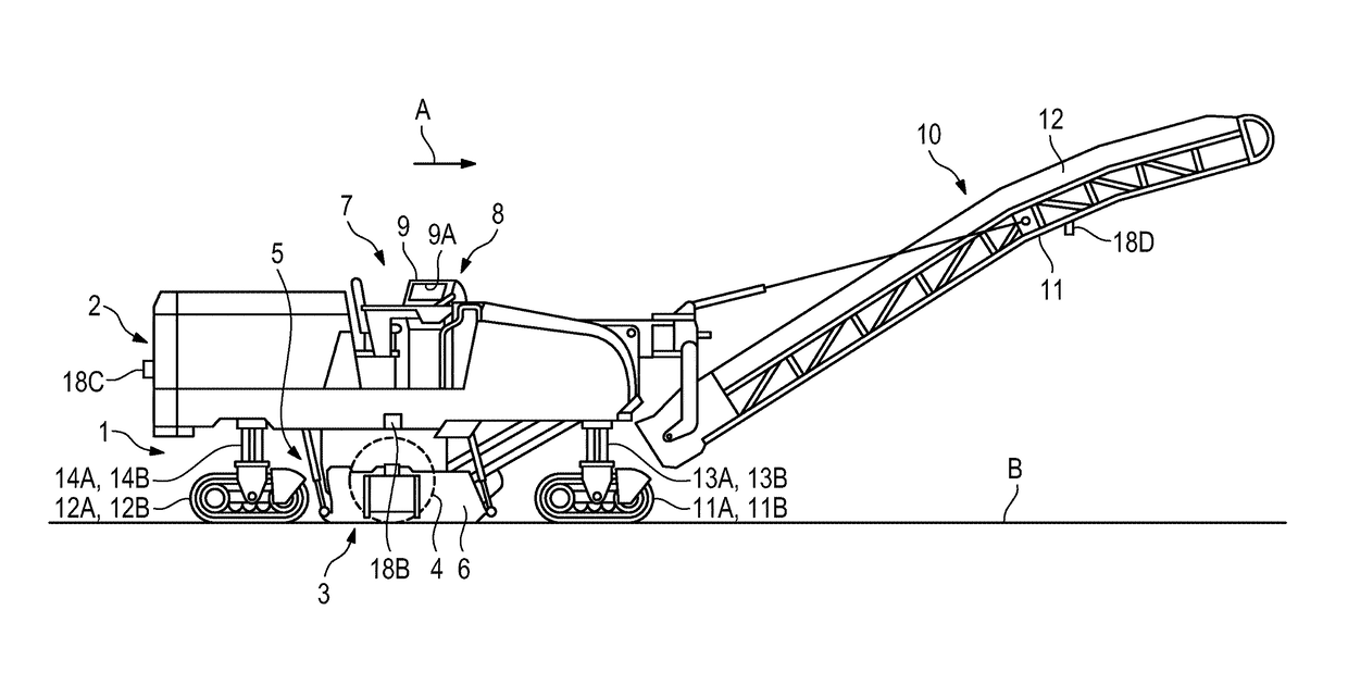
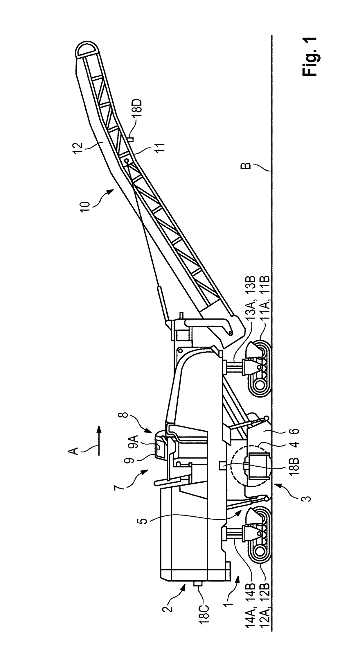
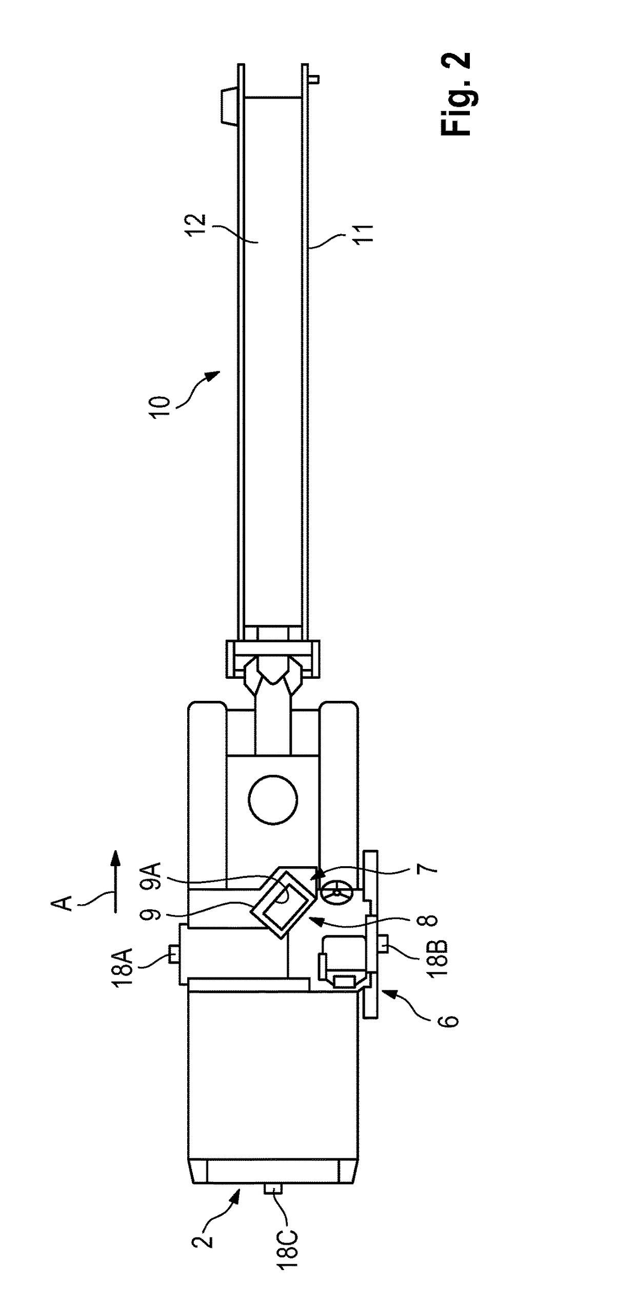
[0045]As an example of an automotive construction machine, FIGS. 1 and 2 show, in a side and plan view, a road milling machine for milling road surfaces, this being a front loader road milling machine. The road milling machine may, however, also be a rear loader road milling machine.

[0046]The construction machine has a machine frame 2 carried by a chassis 1, on which a working device 3 is arranged. The working device 3 has a working roller, this being a milling roller. The milling roller 4, only indicated in FIG. 1, is arranged in a milling roller housing 5. On the left-hand and right-hand side in the working direction A, the milling roller housing 5 is closed by an edge protector 6. The milling roller housing 5 is closed by a hold-down device on the front side in the working direction A, and by a stripper device on the rear side, which devices cannot be seen in FIG. 1. The control stand 7 with a control panel 8 for the machine operator is located on the machine frame above the mill...


PUM


Abstract

The invention relates to an automotive construction machine with a transport device extending in the working direction beyond the machine frame, in particular a road milling machine or surface miner. Moreover, the invention relates to a method for displaying an image of the surroundings of an automotive construction machine. The construction machine according to the invention has an image display device for displaying a bird's eye view image of the surroundings of the construction machine, which image display device has a camera system with a plurality of cameras for recording individual overlapping image regions of the construction machine surroundings from different image recording positions, and an image processing system. The image processing system is configured in such a way that image details of the individual image regions are joined together to form a total image from a bird's eye view. The camera system has at least one camera which is arranged on the transport device in such a way that the viewing direction of the camera is directed in the direction of the machine frame, and at least one further camera which is arranged on the machine frame in such a way that the viewing direction of the camera is directed away from the machine frame. Using the cameras directed into and away from the machine frame, the machine operator obtains a complete surround view, which includes the region covered by the transport device in the working direction in front of the construction machine.

Description

BACKGROUND OF THE INVENTION[0001]1. Field of the Invention[0002]The invention relates to an automotive construction machine with a transport device extending beyond the machine frame in the working direction, in particular a road milling machine or surface miner, which has an image display device for displaying an image of the surroundings of the construction machine. Moreover, the invention relates to a method for displaying an image of the surroundings of an automotive construction machine.[0003]2. Description of the Prior Art[0004]The known construction machines have a machine frame, which is carried by a chassis that has front and rear running gears, and a working device arranged on the machine frame for removing the ground, for example for removing defective road layers (road milling machine), or mining mineral resources (surface miner). The working device may have a milling and / or cutting roller. Lifting devices, which can in each case be retracted or extended, are associated ...

Claims


Application Information

Patent Timeline
Patent Type & Authority Patents(United States)
IPC IPC(8): B60R1/00H04N7/18H04N5/265G06K9/00E02F9/26E02F9/24E02F5/08E02F3/18E02F3/20E01C23/088
CPCB60R1/00E02F3/181E02F3/183E02F3/188E02F3/20E02F5/08E02F9/24E02F9/261G06K9/00791H04N5/265H04N7/181E01C23/088B60R2300/802B60R2300/105B60R2300/303B60R2300/607E01C23/09E21C47/00H04N23/698H04N23/90G06V20/56
Inventor KROLL, HARALDLANGE, HERBERTLENZ, MARTIN
Owner WIRTGEN GMBH
Why Eureka
Try Eureka