Utility vehicle monitoring system

Active Publication Date: 2020-03-19
SAF HOLLAND GMBH
View PDF0 Cites 1 Cited by
  • Summary
  • Abstract
  • Description
  • Claims
  • Application Information

AI Technical Summary

Benefits of technology

[0005]According to the invention, a utility vehicle monitoring system, in particular utility vehicle trailer monitoring system, comprises a utility vehicle subsystem and a central system, wherein the utility vehicle subsystem is arranged and/or is able to be arranged on and/or at a part of a utility vehicle, in particular a utility vehicle trailer, wherein the central system comprises a processing unit and an information transmission unit, wherein the central system is positioned independently of the utility vehicle, wherein the utility vehicle subsystem comprises a transmitter unit, a receiver unit, a processing system and a sensor system, wherein the sensor system is designed to record at least one measured value, in particular a dynamic vehicle characteristic value, and transmit it to the processing system, wherein the transmitter unit and the receiver unit are designed to transfer or to transmit data, in particular the measured values and/or the dynamic vehicle characteristic values, from the processing system to the central system. The utility vehicle monitoring system according to the invention serves in particular to be able to monitor one or a multiplicity of devices present on the utility vehicle. A utility vehicle within the meaning of this invention may in particular be considered to be a roadworthy vehicle whose overall weight is in particular above 3.5 t, preferably above 7 t and very particularly preferably above 12 t. The utility vehicle subsystem of the utility vehicle monitoring system is preferably arranged at least on a part of a utility vehicle, very particularly preferably completely on a utility vehicle; the utility vehicle is in this case in particular a utility vehicle trailer. The utility vehicle subsystem in this case has a sensor system that serves to record measured values. These measured values may in particular be dynamic vehicle characteristic values. Dynamic vehicle characteristic values are in this case values that change, in particular continuously over time, depending on the usage state and/or the wear state and/or the driving state. By way of example, dynamic vehicle characteristic values may be the position of the utility vehicle, the wheel bearing temperature, the current tire pressure, the wear state of the brake system and/or of its subcomponents (brake disk, brake drum and/or brake linings), the speed and the acceleration of the utility vehicle, the position of possible support winches on the utility vehicle, the loading of the axles of the utility vehicle, the pressure in the possible air springs of the utility vehicle, an energy state in an energy storage device (for example compressed air tank and/or battery), the position of the individual axles of the utility vehicle relative to a body of the utility vehicle (for example lifting axles), the fill level of storage tanks (for example brake fluid compensation tank and/or oil level) and/or the brake pressure. To determine these measured values and/or the dynamic vehicle characteristic values, the sensor system preferably has at least one sensor. Such a sensor may be formed for example by a GPS unit, a temperature sensor, a strain gauge, a piezo element, a pressure sensor, a voltage meter and/or an ammeter. The measured value recorded by the sensor system may be transmitted to the processing system within the utility vehicle subsystem in particular by line(s) and/or by radio transmission units. In other words, the sensor system is in particular connected in terms of information to the processing system. The processing system of the utility vehicle subsystem serves to process and/or to forward the measured values. By way of example, the calibration information belonging to a sensor and/or the sensor unit are stored and/or able to be retrieved in the processing system. In other words, the processing system of the utility vehicle subsystem may be designed to convert the voltage signal transmitted by the sensor system into an “actually present”/actual measured value. By way of example, the processing system serves to convert the voltage signal determined by a temperature sensor in the sensor system into an actually present temperature. The processing system is advantageously connected to the transmitter unit and the receiver unit of the utility vehicle subsys

Problems solved by technology

By way of example, it may be the case in the systems known from the prior art that the driver is distracted by the information that is provided and/or that the driver ignor

Method used


Image

  • Utility vehicle monitoring system

Examples


Example

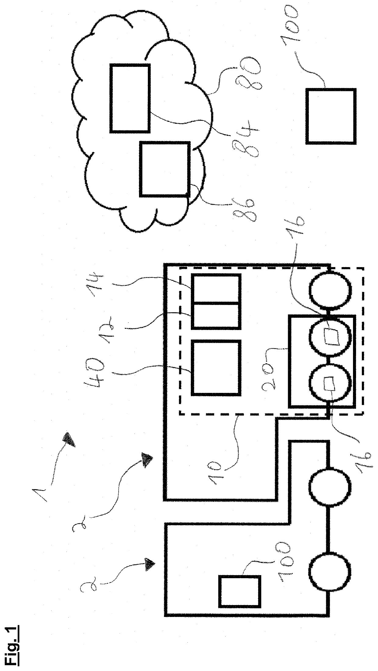
[0019]FIG. 1 shows a utility vehicle monitoring system 1. The utility vehicle monitoring system 1 in this case serves to monitor the utility vehicle 2. In the embodiment illustrated in FIG. 1, the utility vehicle monitoring system 1 serves to monitor the utility vehicle trailer 2. The utility vehicle monitoring system 1 in this case has a utility vehicle subsystem 10 and a central system 80.

[0020]The utility vehicle subsystem 10 contains at least a processing system 40, a transmitter unit 12, a receiver unit 14 and a sensor system 20. In the embodiment illustrated in FIG. 1, the sensor system 20 has two sensors 16 that serve to determine the wheel bearing temperature and the vibration of the axles and the axle load of the utility vehicle trailer 2. The sensor system 20 may transmit the sensor values or measured data determined thereby to the processing system 40 of the utility vehicle subsystem 10 in a wired and / or wireless manner, for example using radio waves. The processing syste...


PUM


Abstract

A utility vehicle monitoring system includes a utility vehicle subsystem and a central system, wherein the utility vehicle subsystem is configured to be arranged proximate a part of a utility vehicle, wherein the central system includes a processing unit and an information transmission unit, wherein the central system is positioned independently of the utility vehicle, wherein the utility vehicle subsystem includes a transmitter unit, a receiver unit, a processing system and a sensor system, wherein the sensor system is configured to record at least one dynamic vehicle characteristic value and transmit the value to the processing system, wherein the transmitter unit and the receiver unit are configured to transmit the at least one dynamic vehicle characteristic value from the processing system to the central system.

Description

CROSS REFERENCE TO RELATED APPLICATION[0001]This application claims priority to the German Patent Application No. 10 2018 122 879.1, filed on Sep. 18, 2018, which is incorporated herein by reference in its entirety.BACKGROUND OF THE INVENTION[0002]The invention relates to a utility vehicle monitoring system, in particular for a utility vehicle trailer.[0003]The prior art already discloses vehicle monitoring systems that serve to monitor the state of individual components of the vehicle. By way of example, such a vehicle monitoring system may be used to monitor the state of the brake linings. The systems known from the prior art in this case have a few disadvantages. By way of example, it may be the case in the systems known from the prior art that the driver is distracted by the information that is provided and / or that the driver ignores important information from the vehicle monitoring system, such that the downtimes of the utility vehicle are at least not able to be reduced using ...

Claims


Application Information

Patent Timeline
IPC IPC(8): G07C5/00G07C5/08G07C5/02
CPCG07C5/008G07C5/02G07C5/0825G07C5/0816G08G1/20
Inventor HÖSSLE, FLORIANPÜTZ, NICOLAS
Owner SAF HOLLAND GMBH
Why Eureka
Try Eureka