Saddle riding type vehicle

a riding type, saddle technology, applied in the direction of axle suspension, vehicle, cycle equipment, etc., can solve the problem of front wheels being locked

Active Publication Date: 2018-10-02
YAMAHA MOTOR CO LTD
View PDF53 Cites 7 Cited by
  • Summary
  • Abstract
  • Description
  • Claims
  • Application Information

AI Technical Summary

Benefits of technology

[0007]Preferred embodiments of the present invention significantly reduce or prevent a difference between the state of the vehicle and a state of the vehicle recognized by the rider when the operation of the linkage is prevented.
[0011]According to a preferred embodiment of the present invention, the notifier continuously notifies a locked state of the linkage. In this way, the rider is more easily aware of the locked state of the linkage.
[0013]Accordingly, it is notified to the rider that the linkage is locked until the linkage is unlocked. Therefore, the rider is easily aware of the state in which the linkage is locked when the pair of front wheels are relatively displaced in the gravity direction.
[0015]Accordingly, when the linkage is locked and the pair of front wheels are relatively displaced in the gravity direction, traveling of the vehicle is prevented. Therefore, traveling of the vehicle is prevented when the pair of front wheels are relatively displaced in the gravity direction.
[0019]According to a preferred embodiment of the present invention, the saddle riding type vehicle further includes a damper. The damper damps vibrations in opposite phases in the pair of front wheels. The lock locks the linkage by preventing operation of the damper and unlocks the linkage by allowing the damper to operate.
[0020]Accordingly, an additional lock is not necessary. Therefore, a compact saddle riding type vehicle is achieved.

Problems solved by technology

However, the front wheels may be locked when they are relatively displaced in the direction of gravity because of a sloped road surface or steps.

Method used


Image

  • Saddle riding type vehicle
  • Saddle riding type vehicle
  • Saddle riding type vehicle

Examples


Embodiment Construction

[0029]Now, saddle riding type vehicles according to preferred embodiments of the present invention will be described in conjunction with the accompanying drawings in which the same or corresponding portions are designated by the same reference characters and their description will not be repeated. Note that the saddle riding type vehicle may be a scooter type vehicle, for example.

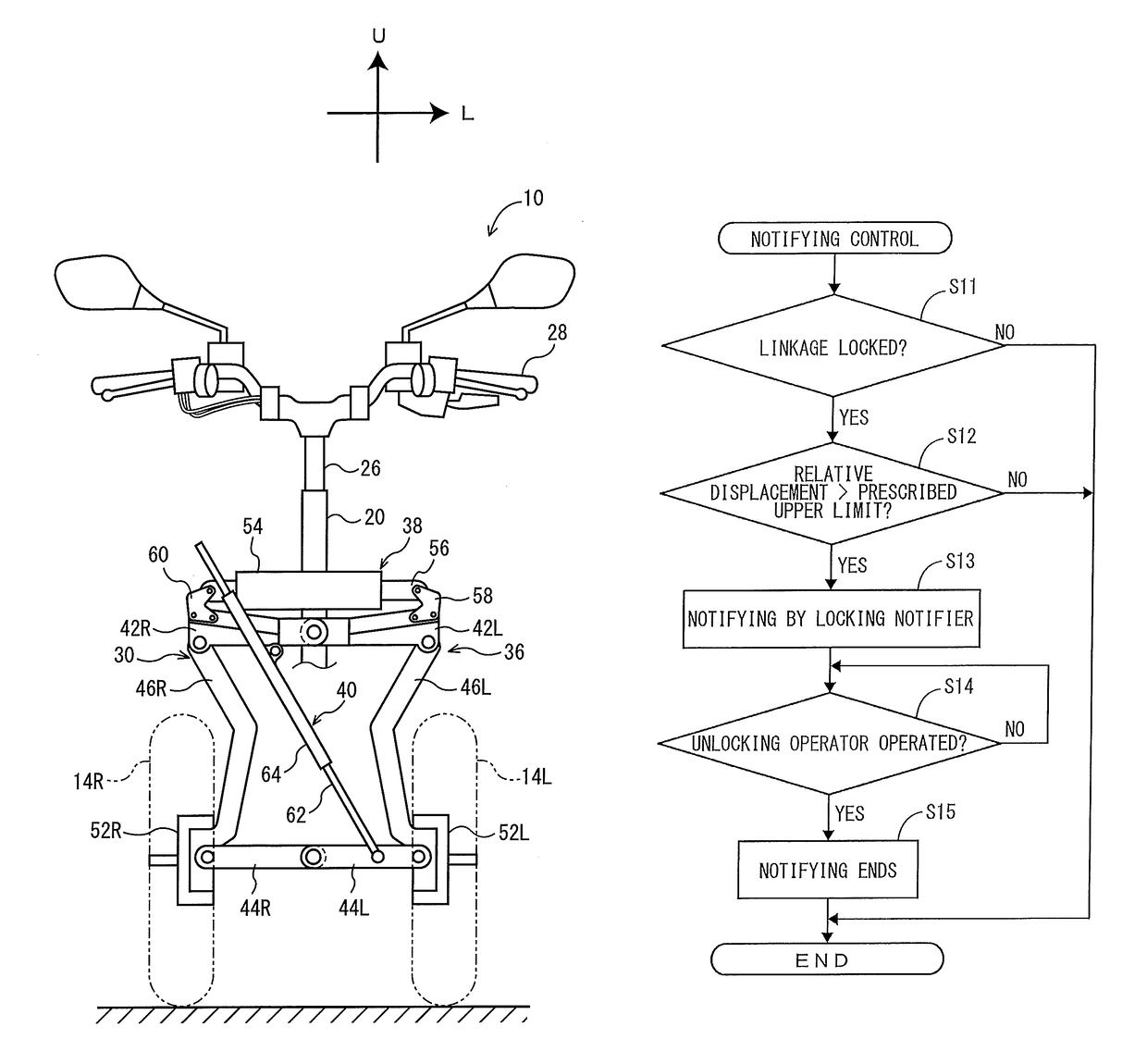
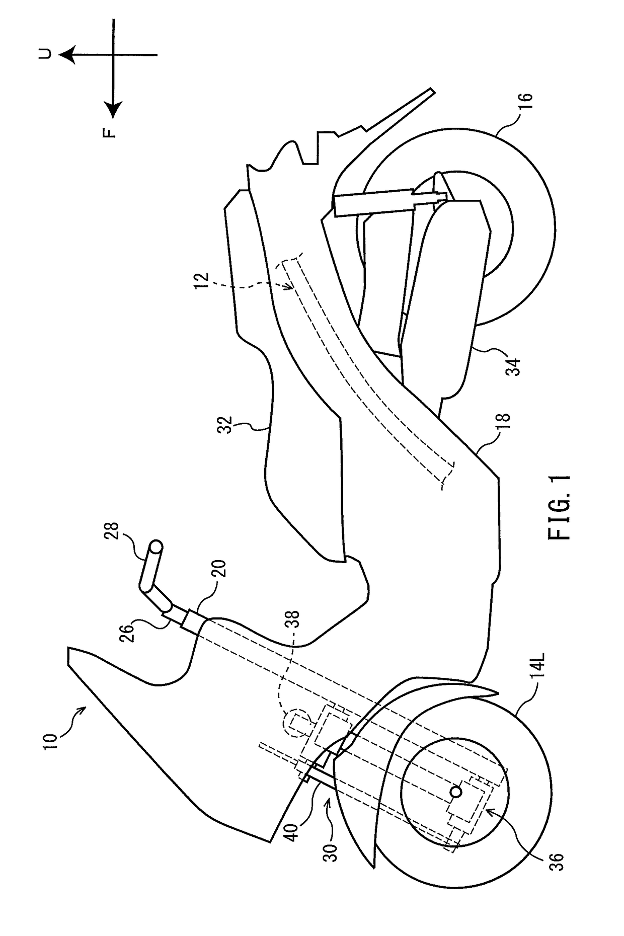
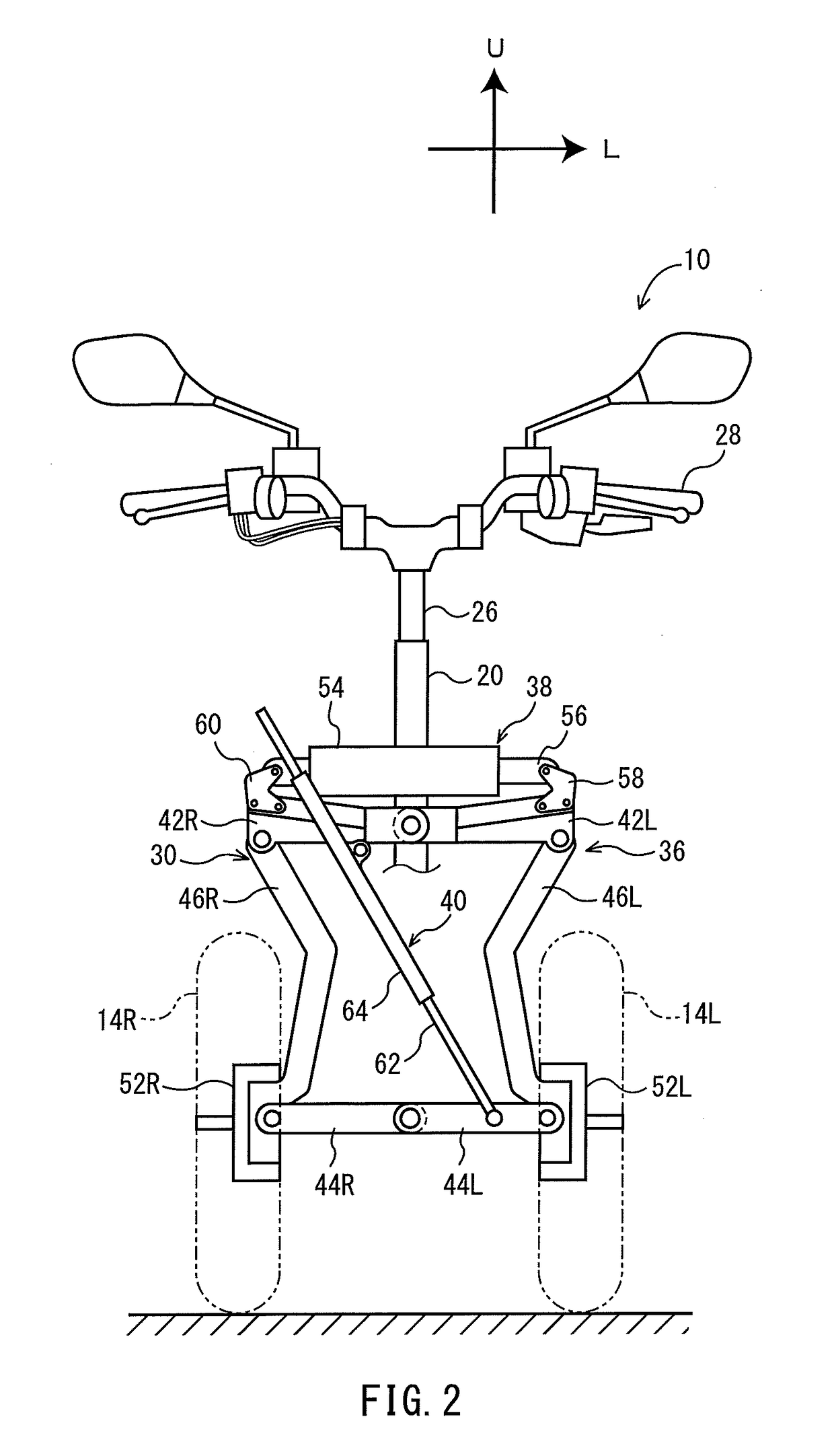
[0030]FIG. 1 is a left side view of a general structure of a saddle riding type vehicle 10 according to a preferred embodiment of the present invention. FIG. 2 is a front view of a general structure of a linkage provided in the saddle riding type vehicle 10. In the following description, the front, back, left, and right refer to positions as seen by the rider seated on a seat 32 of the saddle riding type vehicle 10. In FIG. 1, the arrow F indicates a forward direction of the saddle riding type vehicle 10 and the arrow U indicates an upward direction of the saddle riding type vehicle 10. In FIG. 2, the arrow...


PUM


Abstract

A saddle riding type vehicle that ensures little or no difference between an actual state of the vehicle and a state of the vehicle recognized by the rider includes a vehicle body frame, a pair of front wheels, a linkage, a lock, a controller, and a notifier. The linkage connects the pair of front wheels to the vehicle body frame. The lock locks the linkage by preventing operation of the linkage and unlocks the linkage by allowing the linkage to operate. The controller controls locking and unlocking of the linkage by the lock. The notifier notifies that the linkage is locked when relative displacement between the pair of front wheels in the vertical direction exceeds a prescribed range.

Description

BACKGROUND OF THE INVENTION[0001]1. Field of the Invention[0002]The present invention relates to saddle riding type vehicles and more particularly to a saddle riding type vehicle including a pair of front wheels.[0003]2. Description of the Related Art[0004]An example of a saddle riding type vehicle is a three-wheeled vehicle including a pair of front wheels and a linkage that connects the pair of front wheels to a vehicle body frame. The three-wheeled vehicle is able to turn while leaning by the operation of the linkage.[0005]JP 2005-313876 A discloses an anti-roll device for a three-wheeled vehicle. The anti-roll device includes a brake disk provided integrally with one element of the linkage and a caliper attached to a vehicle body frame. In the anti-roll device, the caliper is used to fix the brake disk to the vehicle body frame. In this way, the operation of the linkage is restricted. This prevents a rolling motion of the vehicle.[0006]The operability of the vehicle greatly diff...

Claims


Application Information

Patent Timeline
Patent Type & Authority Patents(United States)
IPC IPC(8): B62K5/05B62K5/10B62K5/08B62K5/027B62K25/04B62K5/00
CPCB62K25/04B62K5/027B62K5/05B62K5/10B62K5/08B62K2025/047B62K2005/001B62K2025/044
Inventor HARA, NOBUOSHIBUYA, YU
Owner YAMAHA MOTOR CO LTD
Why Eureka
Try Eureka