
Motor vehicle having occlusion detection for ultrasonic sensors

a technology of ultrasonic sensors and motor vehicles, which is applied in the direction of instruments, measurement devices, and using reradiation, can solve the problems of occlusion detection of ultrasonic sensors based on a prolonged decay time, and affecting the accuracy of ultrasonic sensors

Active Publication Date: 2018-10-09
VOLKSWAGEN AG
View PDF34 Cites 2 Cited by
  • Summary
  • Abstract
  • Description
  • Claims
  • Application Information

AI Technical Summary

Benefits of technology

The present invention provides a method for detecting objects near a motor vehicle by using ultrasonic sensors. The method signals an occlusion of the first sensor when there is an ice layer or dirt layer on the vehicle, allowing the sensor to oscillate freely. By checking the decay time and distance value, the method can accurately determine if the object is located on the vehicle or further away. This prevents false alarms and ensures safe operation of the vehicle.

Problems solved by technology

However, in the related art, the ultrasonic sensor is classified as blocked if the duration of the post-pulse oscillation exceeds a predetermined limiting value.
If the diaphragm is iced or dirt is clinging to it, then the flexural stiffness of the diaphragm changes, resulting in an altered decay frequency.
The detection of an occlusion of the diaphragm based on a prolonged decay time has proven to be problematic for the case when an echo of a foreign object strikes the ultrasonic sensor precisely when the amplitude of the natural oscillation drops below the amplitude threshold value mentioned.
Otherwise, the system is not safe.
A further problem with the measurement of the decay time is that the decay time only changes if dirt or ice adheres directly to the diaphragm itself, so that its dynamic behavior changes.
However, in the case of especially thick dirt or ice crusts, it has turned out that these crusts do not co-oscillate with the diaphragm, but instead, the diaphragm detaches from the crust and oscillates freely under it with only a slightly altered decay time.
Thus, even given a thick encrustation, the occlusion of the ultrasonic sensor cannot be detected on the basis of the decay time.

Method used


Image

  • Motor vehicle having occlusion detection for ultrasonic sensors
  • Motor vehicle having occlusion detection for ultrasonic sensors
  • Motor vehicle having occlusion detection for ultrasonic sensors

Examples


Embodiment Construction

[0034]In the exemplary embodiment explained in the following, the described components of the embodiment represent features of the invention that in each case are to be considered individually and independently of each other, and that in each instance likewise further refine the invention independently of each other, and therefore are also to be regarded individually or in a combination other than that indicated as component of the present invention. Moreover, the embodiment described may also be supplemented by further of the features of the invention already described.

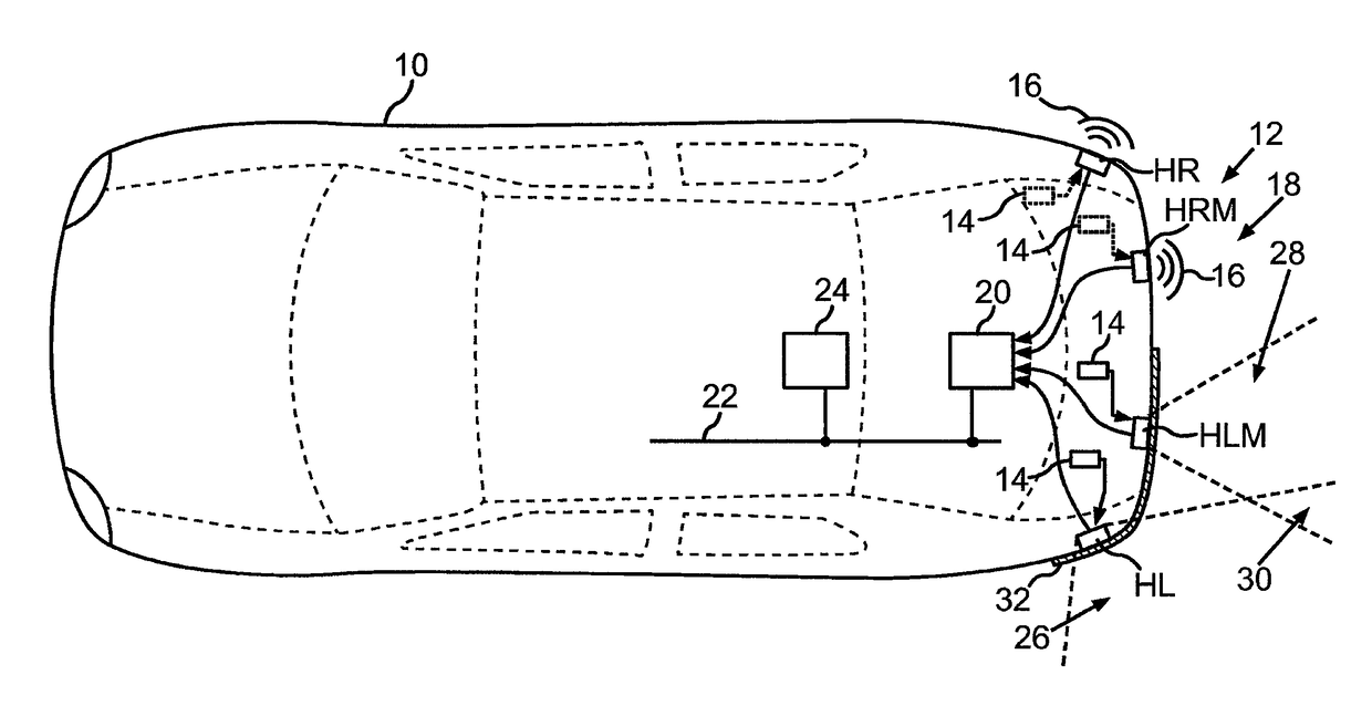
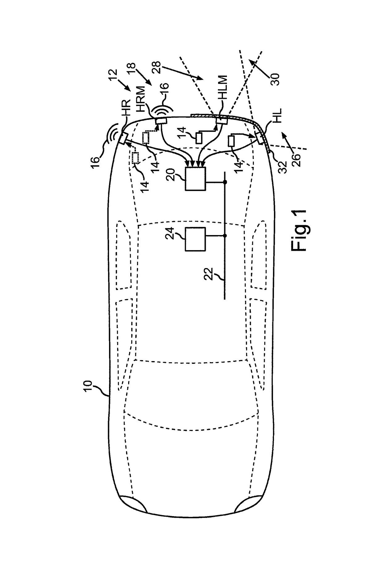
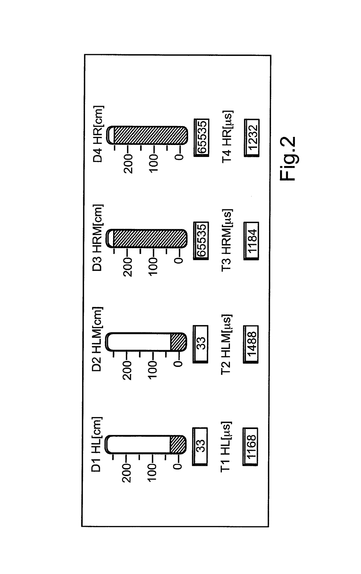
[0035]FIG. 1 shows a motor vehicle 10 from a bird's-eye view; for instance, it may be an automobile, particularly a passenger car. In a tail end 12 of motor vehicle 10, e.g., in a bumper, ultrasonic sensors may be disposed that are denoted in FIG. 1 according to their placement as right rear “HR”, right rear center “HRM”, left rear center “HLM” and left rear “HL”. Ultrasonic sensors HR, HRM, HLM, and HL may be part o...


PUM


Abstract

In a method for checking a first ultrasonic sensor of a motor vehicle for an occlusion, a measuring signal of the first ultrasonic sensor is acquired by an evaluation unit, and from the measuring signal, a decay time of a natural oscillation of the diaphragm of the first ultrasonic sensor, brought about by an excitation pulse, is ascertained. From the measuring signal of either the first ultrasonic sensor or a second ultrasonic sensor, an echo produced by an object located in a sensing range of the first ultrasonic sensor is ascertained, and a distance value of the object is determined on the basis of the echo. An occlusion is signaled if the decay time is less than a predetermined threshold value which would be exceeded if ice and / or dirt were to adhere directly to the diaphragm, and if the distance value is less than a predetermined maximum value.

Description

CROSS REFERENCE TO RELATED APPLICATIONS[0001]The present application claims priority to Application No. 10 2013 223 240.3, filed in the Federal Republic of Germany on Nov. 14, 2013, which is expressly incorporated herein in its entirety by reference thereto.FIELD OF THE INVENTION[0002]The present invention relates to a method for checking an ultrasonic sensor of a motor vehicle as to whether the ultrasonic sensor is occluded by an object located on the motor vehicle, e.g., a layer of ice. The occlusion is ascertained as a function of a decay time, thus, the time for a natural oscillation of the diaphragm to die out after an excitation pulse has been applied to it for emitting an ultrasonic signal.BACKGROUND INFORMATION[0003]It is likewise known from published German patent application document 10 2010 021 960 A1 to measure the time duration of a post-pulse oscillation in order to detect a blocked state of an ultrasonic sensor. However, in the related art, the ultrasonic sensor is cl...

Claims


Application Information

Patent Timeline
Patent Type & Authority Patents(United States)
IPC IPC(8): G01S7/52G01S7/56G01S15/87G01S15/93G01S15/88G01S15/931
CPCG01S15/878G01S7/52004G01S7/56G01S15/931G01S2015/938G01S2007/52009G01S2015/932
Inventor MOSSAU, DANIELBAUMANN, PETERCARSTEN, HEINECKETANNER, MANUELSANNY, KNUT
Owner VOLKSWAGEN AG
Learn More