
Electric power tool

a technology of electric power tools and power tools, applied in the field of electric power tools, can solve the problems of unnecessarily increasing power consumption, vibration and noise, and achieve the effect of excellent work efficiency

Active Publication Date: 2018-10-16
KOKI HLDG CO LTD
View PDF21 Cites 723 Cited by
  • Summary
  • Abstract
  • Description
  • Claims
  • Application Information

AI Technical Summary

Benefits of technology

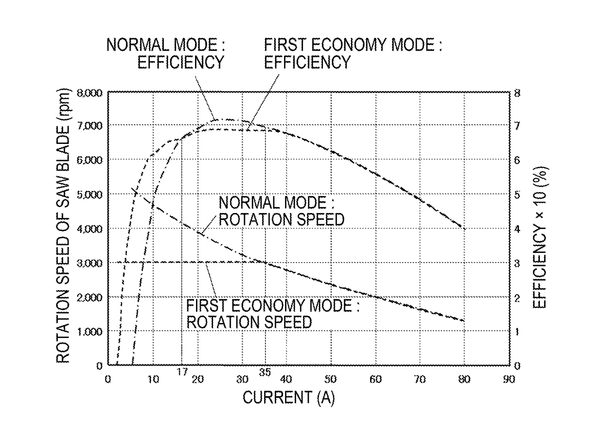
[0004]The present invention has been made in view of the above-described circumstances, and an aspect of the present invention provides an electric power tool which can control a brushless motor at multiple rotation speeds and is excellent in work efficiency.
[0020]According to the above configuration, it is possible to provide an electric power tool capable of controlling a brushless motor at multiple rotation speeds and excellent in work efficiency.

Problems solved by technology

If the rotation speed during no-load increases, there are problems that vibration and noise increase and power consumption unnecessarily increases.
These problems are not limited to a circular saw, but are common to other electric power tools such as a grinder.

Method used


Image

  • Electric power tool
  • Electric power tool
  • Electric power tool

Examples


Embodiment Construction

[0039]Hereinafter, embodiments of the present invention will be described with reference to the accompanying drawings. Components, members, and the like shown in the drawings and identical or equivalent to each other are denoted by the same reference symbol and may not be repeatedly described. The embodiments do not limit the invention and are illustrative, and all features to be described in the embodiments, and combinations thereof may not be the essential features of the invention.

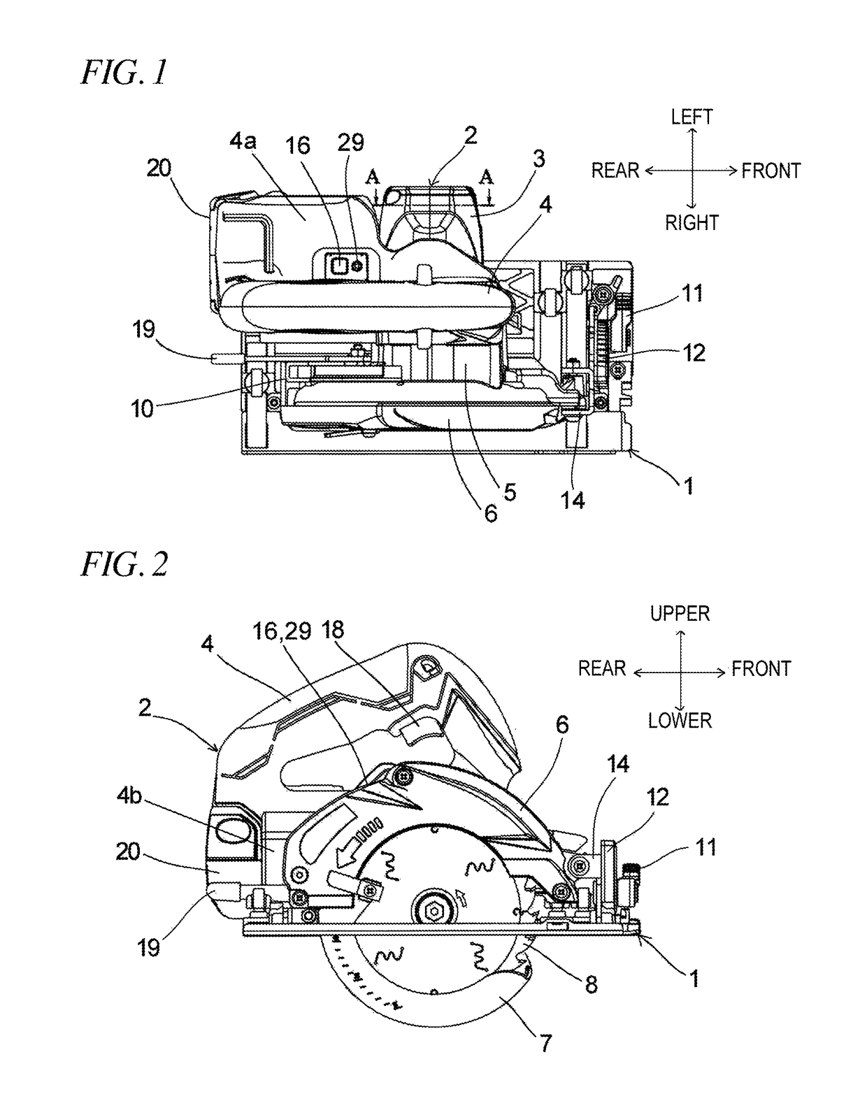
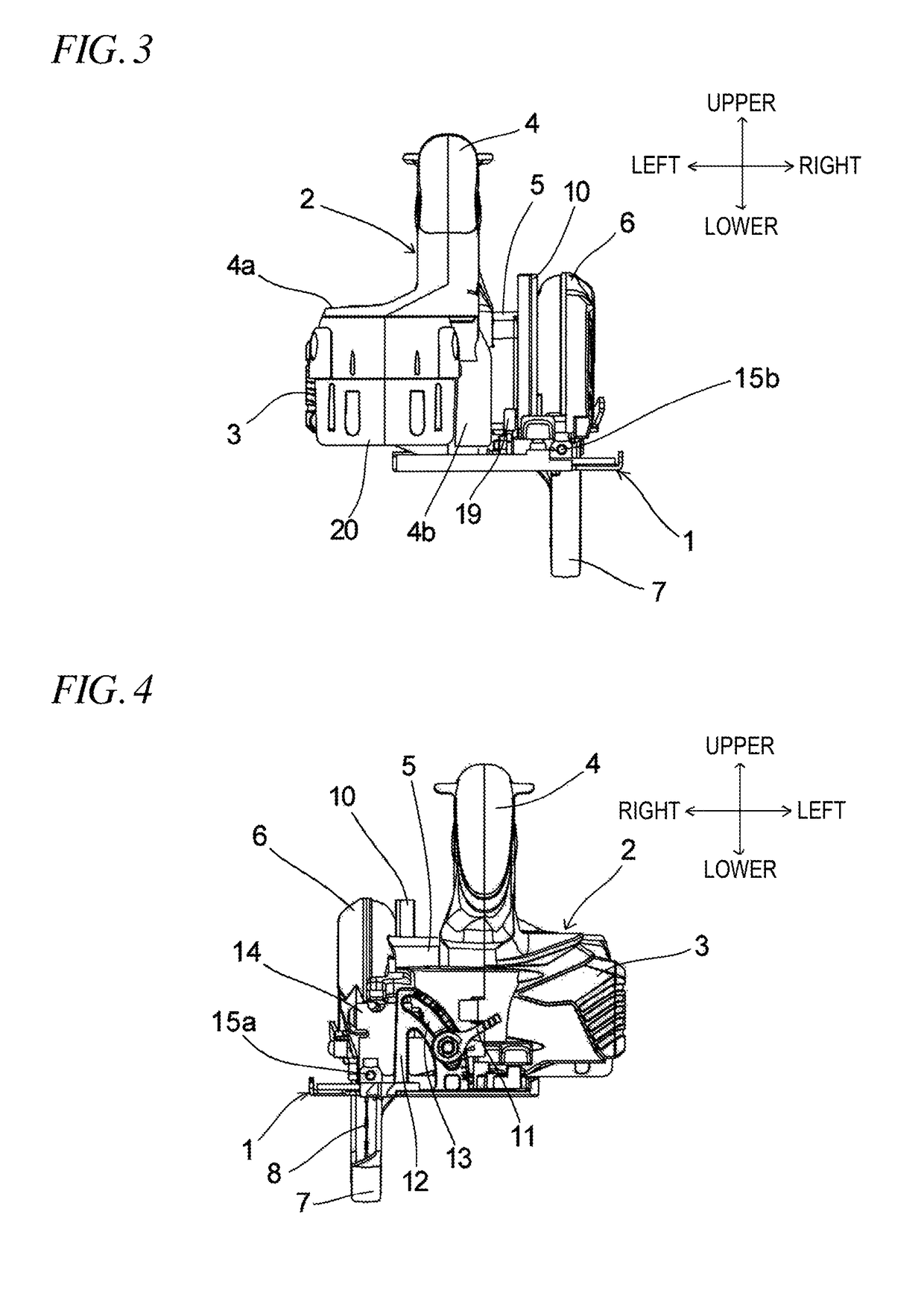
[0040]FIGS. 1 to 4 are a plan view, a side view, a rear view, and a front view showing a cordless circular saw according to an embodiment of the present invention, respectively. FIG. 5 is a first plan view of the cordless circular saw where a portion thereof is shown as a cross-section. FIG. 6 is a second plan view of the cordless circular saw where another portion thereof is shown as a cross-section. FIG. 7 is a cross-sectional view taken along a line A-A of FIG. 1.

[0041]The cordless circular saw of th...


PUM

PropertyMeasurementUnit
load currentaaaaaaaaaa
poweraaaaaaaaaa
rotation speedaaaaaaaaaa

Abstract

An electric power tool includes a brushless motor, a control unit configured to control power supply to the brushless motor, a rotary tool configured to be rotated by the brushless motor, a rotation speed detecting unit configured to detect a rotation speed of the brushless motor, a main switch configured to transmit, to the control unit, an ON / OFF signal for switching between driving and stopping of the brushless motor, and a mode switching unit configured to transmit, to the control unit, a mode switching signal for switching between multiple modes of rotation control of the brushless motor, the control unit is configured to perform the rotation control of the brushless motor in any one of the multiple modes including at least a high-speed mode and a low-speed mode.

Description

TECHNICAL FIELD[0001]The present invention relates to an electric power tool such as a circular saw.BACKGROUND ART[0002]In a circular saw, for example, in order to increase cutting efficiency, it is necessary to increase the rotation speed of a saw blade during cutting. To this end, it is necessary to increase the rotation speed during no-load. Even at the markets, in order to emphasize a smooth cutting performance, the manufactures tend to appeal the high-speed rotation during no-load.[0003]If the rotation speed during no-load increases, there are problems that vibration and noise increase and power consumption unnecessarily increases. These problems are not limited to a circular saw, but are common to other electric power tools such as a grinder.SUMMARY OF INVENTIONTechnical Problem[0004]The present invention has been made in view of the above-described circumstances, and an aspect of the present invention provides an electric power tool which can control a brushless motor at mult...

Claims


Application Information

Patent Timeline
Patent Type & Authority Patents(United States)
IPC IPC(8): B25F5/00B23D47/12B23D59/00
CPCB23D59/001B25F5/001B25F5/00B23D47/12
Inventor YOSHIDA, KENICHIROUONOSE, AKIRAKURAGANO, SHINJI
Owner KOKI HLDG CO LTD
Learn More