Unmanned aerial vehicle
a technology for unmanned aerial vehicles and aircraft, which is applied in the direction of aircrafts, wheel arrangements, transportation and packaging, etc., can solve the problems of expensive and difficult to obtain mini-unmanned aerial vehicles typified by unmanned helicopters for industrial us
- Summary
- Abstract
- Description
- Claims
- Application Information
AI Technical Summary
Benefits of technology
Problems solved by technology
Method used
Image

Examples
first embodiment
(General Description of Configuration)
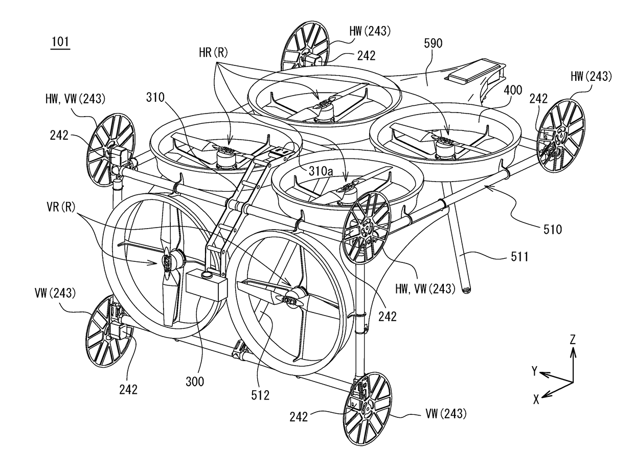
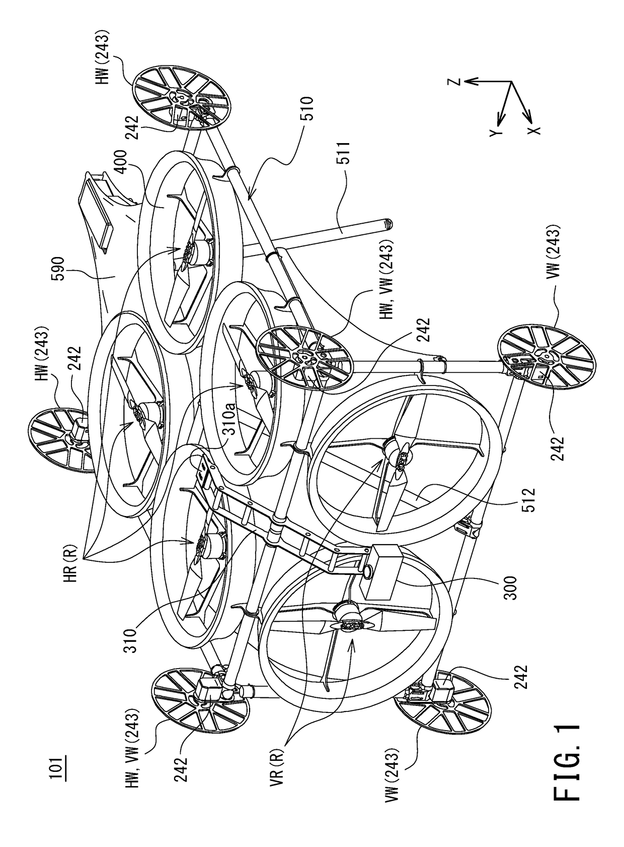
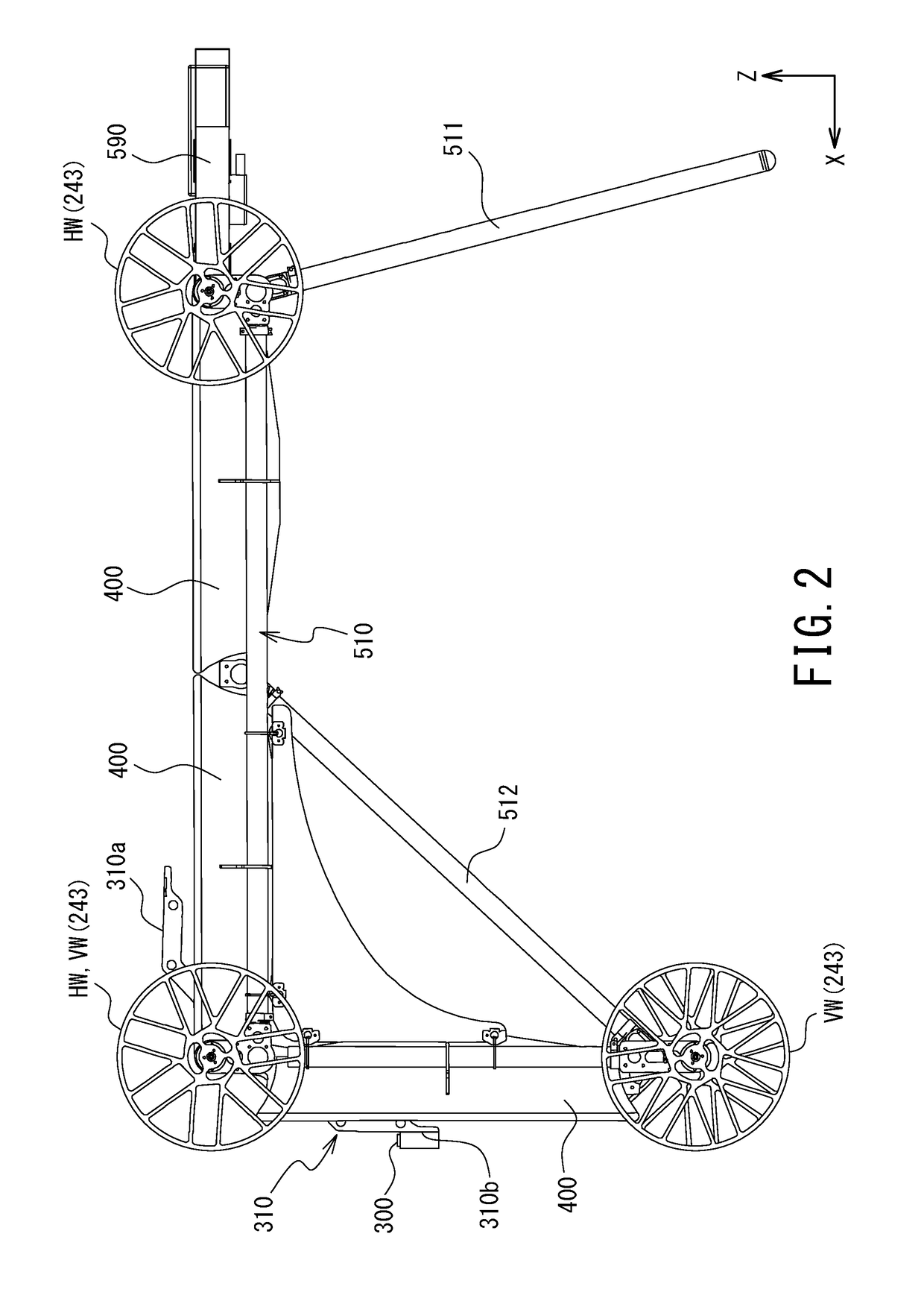
[0030]FIG. 1 is a perspective view depicting an external appearance of a multicopter 101 pertaining to a first embodiment and FIG. 2 is a side view depicting an external appearance of the multicopter 101.
[0031]The multicopter 101 is equipped with a plurality of rotors R and these rotors R are comprised of four horizontal rotors HR and two vertical rotors VR. The horizontal rotors HR and vertical rotors VR are disposed such that the axes of rotation of the horizontal and vertical rotors extend in directions perpendicular to each other. The four horizontal rotors HR are arranged horizontally and disposed right and left and front and back in two rows. The two vertical rotors VR are disposed, arranged right and left with their intake sides oriented toward the front. All the horizontal rotors HR and vertical rotors VR are ducted fans whose circumference is surrounded by a duct 400. Now, in the present invention, “horizontal rotors” refer to rotors in...
second embodiment
[0054]A second embodiment of an unmanned aerial vehicle of the present invention is described below with the aid of a drawing. In the following description, a component having the same or a similar function as in the foregoing embodiment is assigned the same reference designator as in the foregoing embodiment and its detailed description is omitted.
[0055]FIG. 5 is a per view depicting an external appearance of a multicopter 102 pertaining to the second embodiment. The multicopter 102 is an airframe that is equipped with only four horizontal rotors HR as rotors R. On the air intake side (upper) of these horizontal rotors HR, four tires HW for a ceiling surface which are tires 243 equipped with a motor 242 are disposed.
[0056]The multicopter 102 includes a frame body 520 to support the horizontal rotors HR and the tires HW for a ceiling surface. The frame body 520 includes an outer frame 521 which is a frame body having a generally cuboid shape and comprised of pipe members and a gener...
third embodiment
[0058]A third embodiment of an unmanned aerial vehicle of the present invention is described below with the aid of a drawing. In the following description, a component having the same or a similar function as in the foregoing embodiment is assigned the same reference designator as in the foregoing embodiment and its detailed description is omitted.
[0059]FIG. 6 is a schematic diagram depicting a method of home delivery using a multicopter 103 pertaining to a third embodiment to deliver a parcel L to a balcony of general collective housing. The parcel L is secured on the top of the multicopter 103. Now, a basic configuration and functions of the multicopter 103 are the same as the multicopter 101, except for features of the multicopters 103 which are described below.
[0060]The multicopter 103 of the present embodiment flies to a location of collective housing which is a destination of home delivery, using the GPS receiver 133. The multicopter 103 is equipped with fixed wings 700 and th...
PUM
 Abstract
Description
Claims
Application Information
 - R&D Engineer
- R&D Manager
- IP Professional
- Industry Leading Data Capabilities
- Powerful AI technology
- Patent DNA Extraction
Browse by: Latest US Patents, China's latest patents, Technical Efficacy Thesaurus, Application Domain, Technology Topic.
© 2024 PatSnap. All rights reserved.Legal|Privacy policy|Modern Slavery Act Transparency Statement|Sitemap