
Electronic device and hinge structure

Active Publication Date: 2018-10-16
ACER INC
View PDF13 Cites 14 Cited by
  • Summary
  • Abstract
  • Description
  • Claims
  • Application Information

AI Technical Summary

Benefits of technology

The invention is about a hinge structure on an electronic device that allows it to fold and support itself on a plane. The hinge structure uses two resilient members that provide elastic forces to keep the device in a folded state. When the device is removed from the plane, the bracket automatically returns to its expanded state. The invention improves the decay rate of the hinge structure during life-cycle testing, which enhances its lifespan.

Problems solved by technology

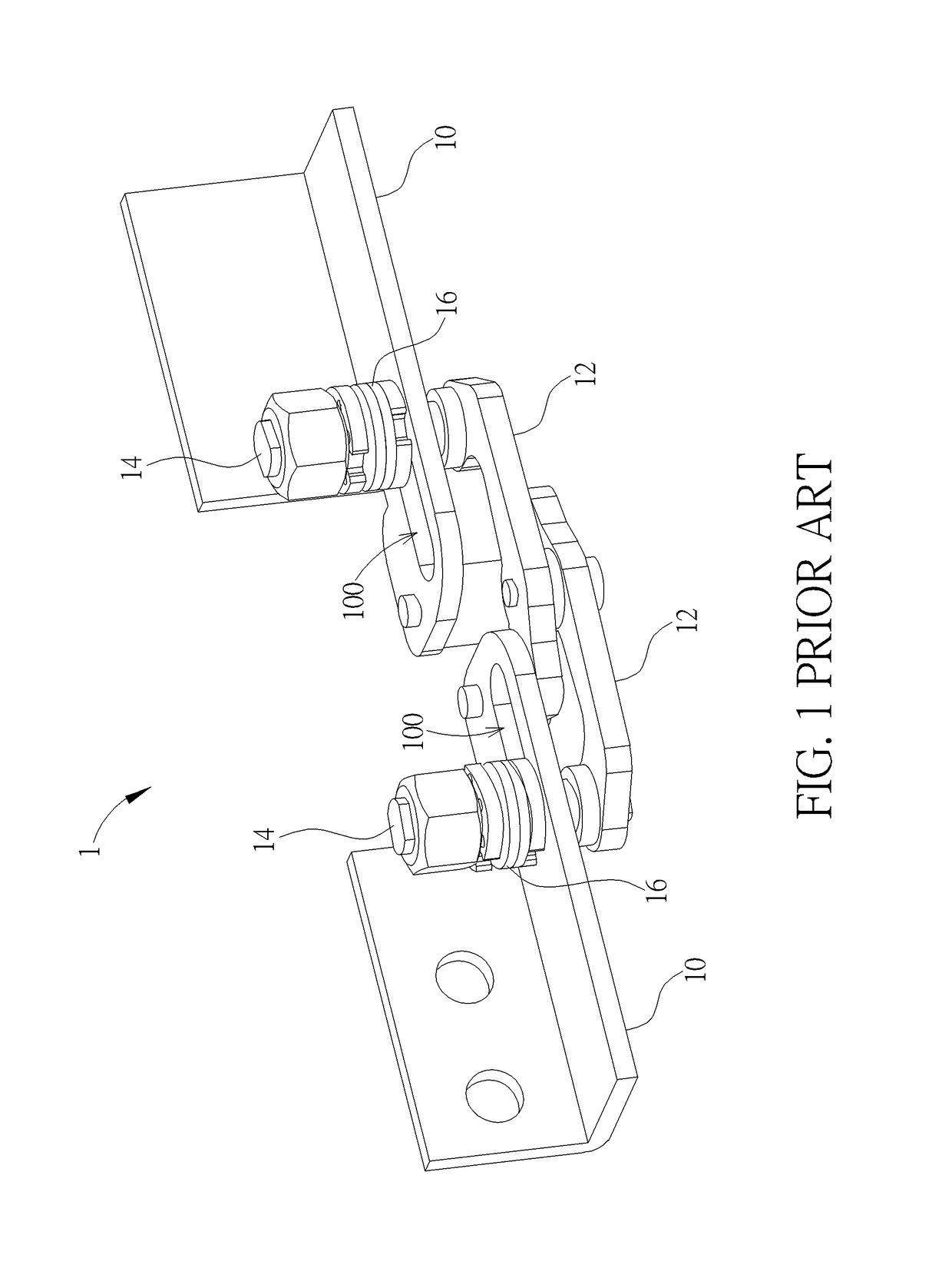
However, the friction may abrade the concave-convex resilient member 16 and then the friction may decay, such that the hinge structure 1 may not pass life-cycle test.

Method used


Image

  • Electronic device and hinge structure
  • Electronic device and hinge structure
  • Electronic device and hinge structure

Examples


Embodiment Construction

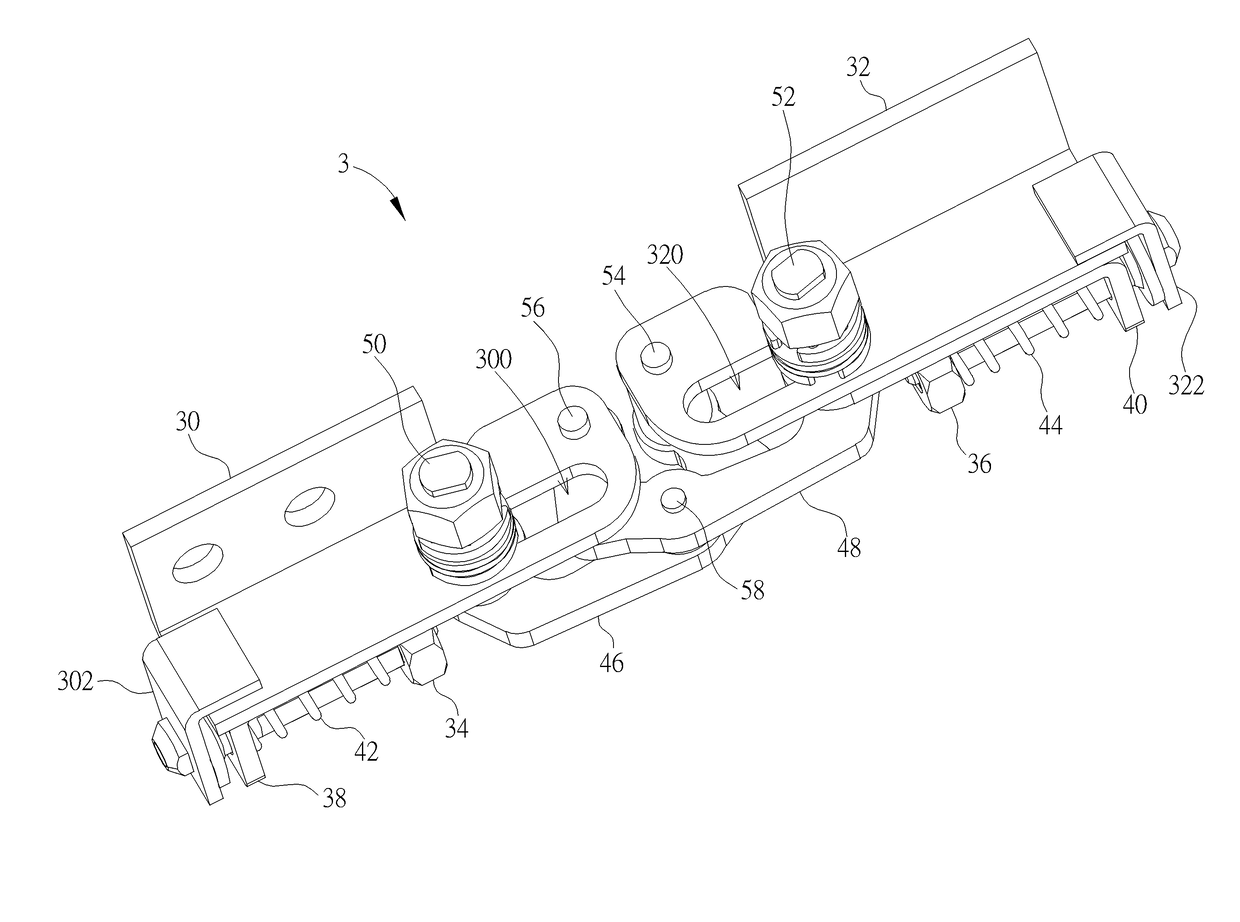
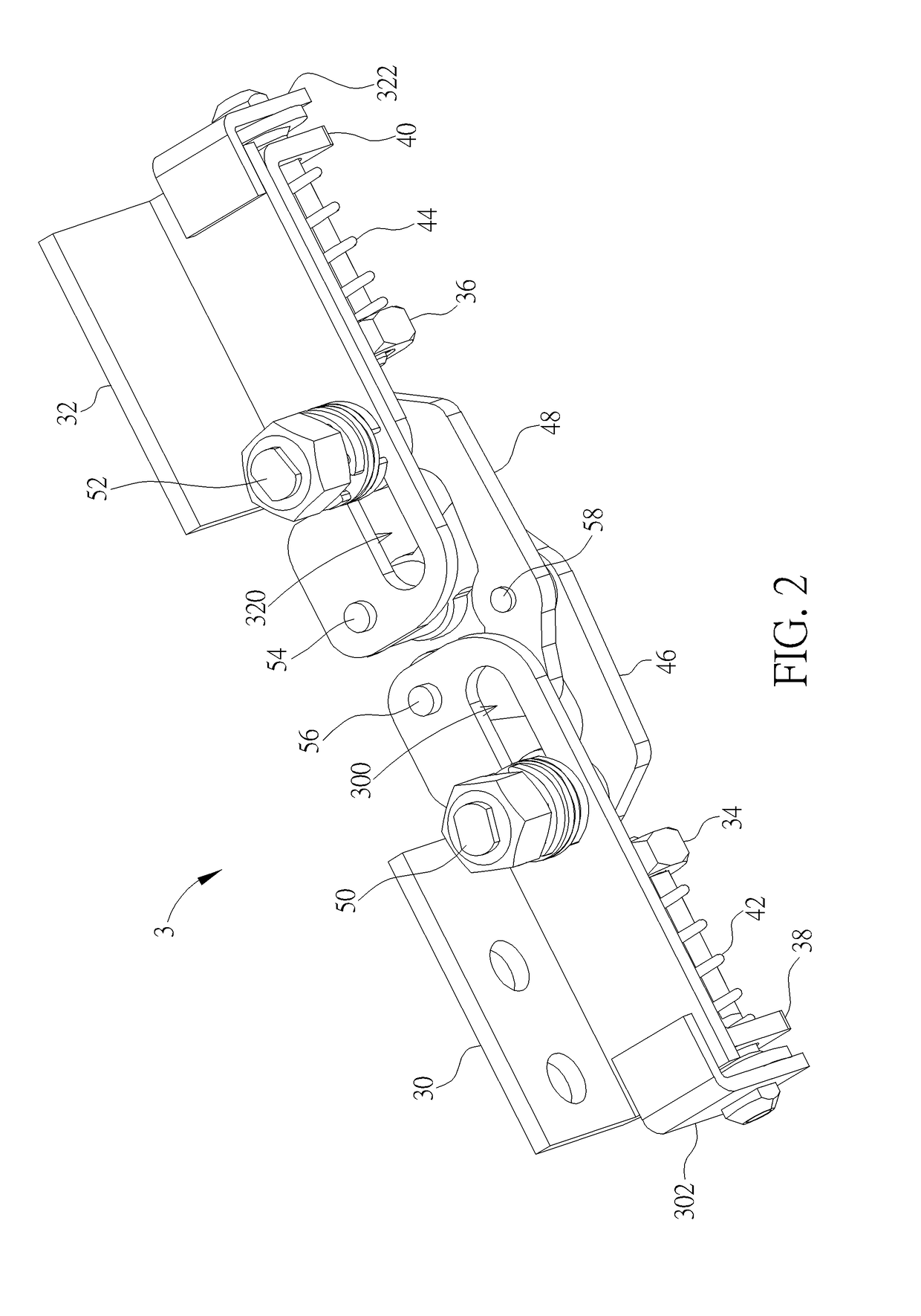
[0019]Referring to FIGS. 2 to 5, FIG. 2 is a perspective view illustrating a hinge structure 3 according to an embodiment of the invention, FIG. 3 is a perspective view illustrating the hinge structure 3 shown in FIG. 2 from another viewing angle, FIG. 4 is a top view illustrating the hinge structure 3 shown in FIG. 3, and FIG. 5 is a schematic view illustrating the first bracket 30 and the second bracket 32 shown in FIG. 4 being folded with respect to each other.

[0020]As shown in FIGS. 2 to 5, the hinge structure 3 comprises a first bracket 30, a second bracket 32, a first fixing member 34, a second fixing member 36, a first linking member 38, a second linking member 40, a first resilient member 42, a second resilient member 44, a first linking bar 46, a second linking bar 48, a first sliding member 50 and a second sliding member 52.

[0021]The first bracket 30 has a sliding groove 300 and the second bracket 32 has a second sliding groove 320. In this embodiment, the first bracket 30...


PUM


Abstract

A hinge structure includes a first bracket, a second bracket, a first fixing member connected to the first bracket, a second fixing member connected to the second bracket, a first linking member, a second linking member, a first resilient member, a second resilient member, a first linking bar pivotally connected to the second bracket, a second linking bar pivotally connected to the first bracket, a first sliding member and a second sliding member. The first linking member and the first resilient member are disposed on the first fixing member. The second linking member and the second resilient member are disposed on the second fixing member. The first linking bar is pivotally connected to the second linking bar. The first sliding member is connected to the first linking member and the first linking bar. The second sliding member is connected to the second linking member and the second linking bar.

Description

BACKGROUND OF THE INVENTION1. Field of the Invention[0001]The invention relates to an electronic device and a hinge structure and, more particularly, to a hinge structure with auto-return function and an electronic device equipped with the hinge structure.2. Description of the Prior Art[0002]A hinge structure nowadays is used widely in various applications. For example, a door, a notebook computer, and so on is equipped with the hinge structure, so as to achieve open / close function. Referring to FIG. 1, FIG. 1 is a perspective view illustrating a hinge structure 1 of the prior art. As shown in FIG. 1, the hinge structure 1 consists of two brackets 10, two linking bars 12 and two sliding members 14. The linking bar 12 can drive the sliding member 14 to slide within a sliding groove 100 of the bracket 10, such that the two brackets 10 can be folded with respect to each other. The hinge structure 1 generates friction to function by means of a concave-convex resilient member 16 disposed...

Claims


Application Information

Patent Timeline
IPC IPC(8): E05D15/32H05K5/02F16M11/10E05D3/18F16C11/04E05D11/00F16M13/00
CPCF16M13/005F16C11/04E05D3/18F16M11/10H05K5/0226E05D11/00E05Y2201/474E05Y2900/606E05D3/186E05D11/087E05F1/105E05Y2201/422G06F1/1681E05Y2999/00
Inventor WU, CHUN-HSIENCHEN, SHUN-BINCHEN, WEN-CHIEH
Owner ACER INC
Learn More