
Detection device and method of using the same

a detection device and detection method technology, applied in the direction of instruments, withdrawing sample devices, material analysis, etc., can solve the problems of inability to prompt specimen detection and inability to detect further, so as to facilitate detection counting and determination, prevent the position change of the transferring chamber, and facilitate operation.

Active Publication Date: 2018-10-23
ABBOTT RAPID DIAGNOSTICS INT UNLTD
View PDF7 Cites 0 Cited by
  • Summary
  • Abstract
  • Description
  • Claims
  • Application Information

AI Technical Summary

Benefits of technology

The present invention has the benefits of displaying a signal when a detection is activated, making it easier to count and determine. It also prevents changes in the position of the transferring chamber, and is easy to operate when the detection is activated.

Problems solved by technology

On the other hand, if the indicating element indicates that the detection is already activated prior to detecting, it means that the detection device has been operated incorrectly, and such a detection device and its detecting element are therefore deemed used and cannot be used for detection any more.
If without the provisional “protection” by the blocking element and if inadvertent movement occurs, the detection could not be further carried out and prompt detection of specimen would therefore not be achieved.

Method used


Image

  • Detection device and method of using the same
  • Detection device and method of using the same
  • Detection device and method of using the same

Examples


example 1

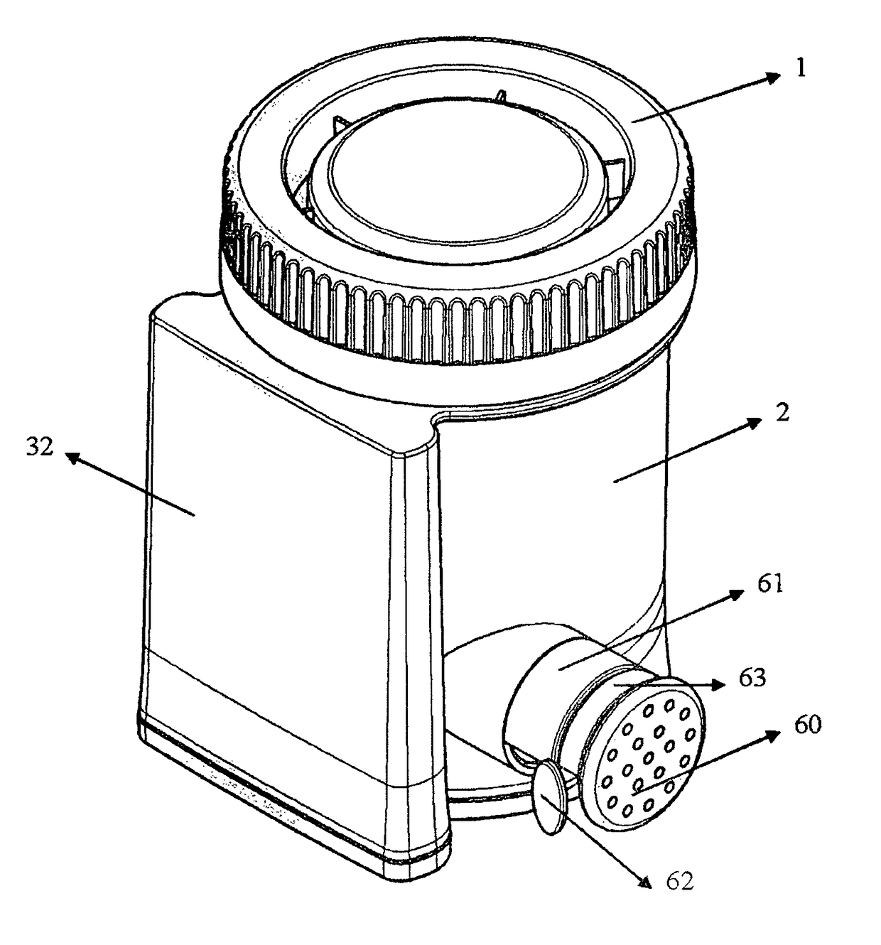
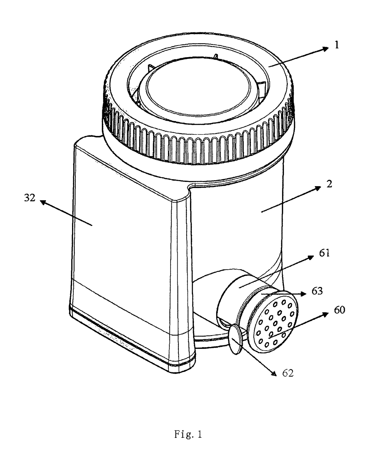
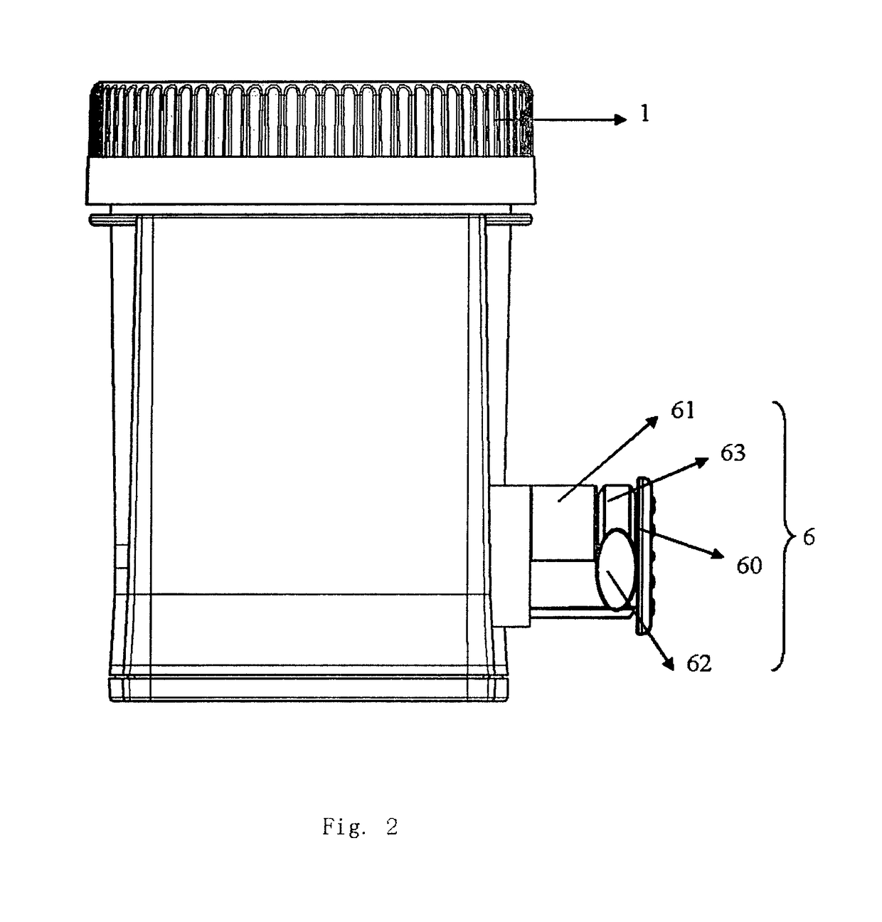
[0035]As illustrated in FIGS. 1, 2 and 3, the detection device 100 comprises the collecting chamber 21 and the detecting chamber 32, and the piston chamber (transferring chamber) 22 that transfers the liquid in the collecting chamber 21 to the detecting chamber 32. The collecting chamber 21 includes the cup body 2 that has a cup mouth 20 at the top and a cup chamber inside; the cup mouth 20 has a cup lid 1, the cup lid 1 and the cup mouth 20 have cross sections of round shape, and the cup 1 is connected with the cup mouth 20 through the screw thread 201 of the latter. The bottom of the detecting chamber 32 has a cup seat 3 provided with a socket 34 having two support bars 33 inside for supporting the protrusion 56 on the plugboard such that the test card 5 having testing strips can partially hang over the socket 34 of the cup seat. The benefit of this configuration is that the detection reagent strip 52 can maintain a perpendicularly hanging status during the process that the detect...


PUM

PropertyMeasurementUnit
central angleaaaaaaaaaa
lengthaaaaaaaaaa
speedaaaaaaaaaa

Abstract

A detection device (100) comprises a detecting chamber (32) containing a detecting element for analyzing whether a specimen containing an analyte, and an indicating element (8) displaying whether the detection is activated. The method for using the detection device (100) is also disclosed.

Description

CROSS REFERENCE TO RELATED APPLICATIONS[0001]This application is a 35 USC § 371 National Stage application of International Application No. PCT / CN2010 / 001227 filed Aug. 13, 2010, now pending; which claims the benefit under 35 USC § 119(a) to China Patent Application No. CN200920191918.3 filed Aug. 13, 2009, China Patent Application No. CN200910102113.1 filed Aug. 13, 2009 and China Patent Application No. CN200920191917.9 filed Aug. 13, 2009. The disclosure of each of the prior applications is considered part of and is incorporated by reference in the disclosure of this application.TECHNICAL FIELD[0002]The present invention relates generally to a detection device. More specifically, it relates a detection device for detecting illegal drugs.BACKGROUND[0003]Illegal drugs are easily accessible to ordinary people these days, and their uses are seen more frequently. To ensure safety environments in works and fair competitions in sports, more and more often collection and detection devices...

Claims


Application Information

Patent Timeline
Patent Type & Authority Patents(United States)
IPC IPC(8): G01N21/00G01N1/10G01N33/493G01N1/02G01N33/487
CPCG01N1/10G01N33/493G01N2001/027G01N2001/022G01N33/4875
Inventor TARPEY, CHRISTOPHERPARSONS, MARY CATHERINEGOU, LIJIANHU, HAIPENGGAO, FEIWU, YINFEI
Owner ABBOTT RAPID DIAGNOSTICS INT UNLTD
Learn More