Archery bow axle assembly

Active Publication Date: 2018-11-13
GRACE ENG
View PDF34 Cites 4 Cited by
  • Summary
  • Abstract
  • Description
  • Claims
  • Application Information

AI Technical Summary

Benefits of technology

This patent is about an axle assembly for airplanes and archery bows. The assembly includes cam spacers and rims that compress the bearings between the parts. This clamps the components together, improving the efficiency of the cam and reducing noise. The assembly also allows other components to rotate freely, which is important for consistent cam rotation and a smooth draw of the bow. Additionally, the assembly can be used on split limb bows and still provide torsional rigidity comparable to a solid limb bow.

Problems solved by technology

One drawback of split limb systems, (and even some solid limb systems) is that most have a floating axle system that takes up some, but not all of the slop and spacing between different components mounted between the ends of the axle.
The spacers are helpful in that they can locate the cam components in a general lateral position relative to one another, however, with this floating axle system, it is virtually impossible to eliminate all the gaps between cam components on the axle without compressing and binding bearings disposed along the axle that assist in rotation of the cams.
Thus, virtually all of these floating axle systems have gaps between the components on the axle.
Accordingly, the cams and components can slide laterally along the axle, which can lead to inconsistent and / or imprecise rotation of the cams.
While some claim that this threaded axle system provides zero tolerance and zero space between the components, it is believed that in reality, there is some space between the elements, especially when the components wear at the points of contact over time.
This can lead to larger unwanted gaps and lateral movement along the axle, which again generates inconsistent and sometimes slightly misaligned rotation of the components on the axle.
Further, these systems are designed so that the tightening of the fastener does not compress the components along the axle (the components are merely very close to one another), which compression can crush the bearings such that the cam will not rotate well in this system.
In most cases, these systems are designed so the fastener bottoms out before putting any compression on the components along the axle, which again results in those systems failing to eliminate all the slack and gaps in the stack up of components along the axle.

Method used


Image

  • Archery bow axle assembly
  • Archery bow axle assembly
  • Archery bow axle assembly

Examples


Embodiment Construction

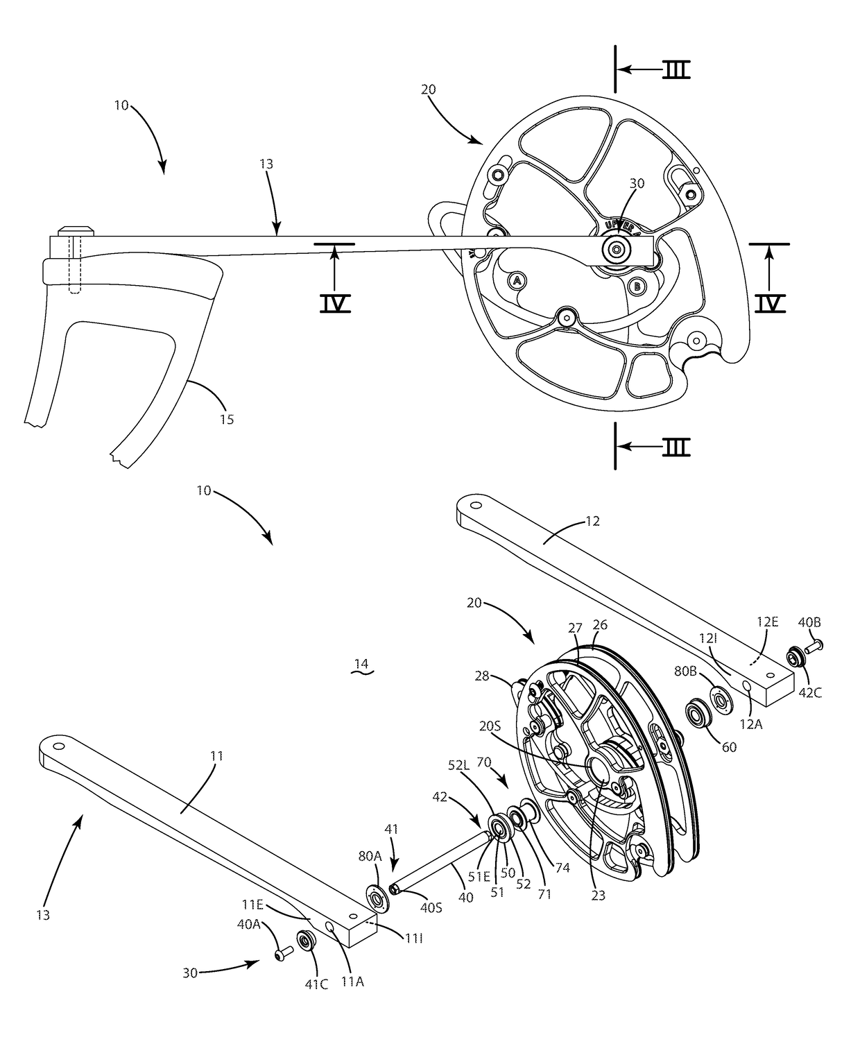
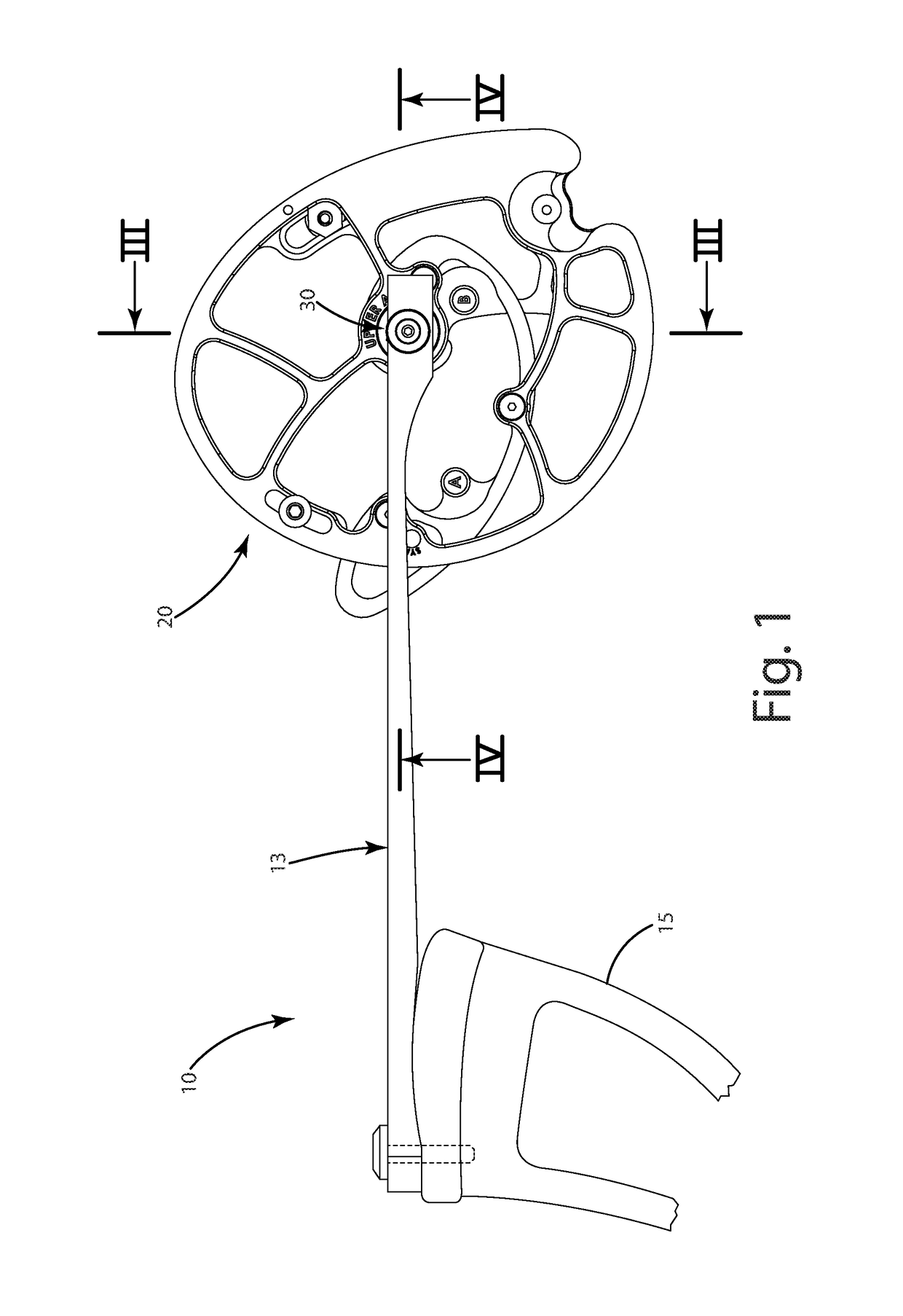
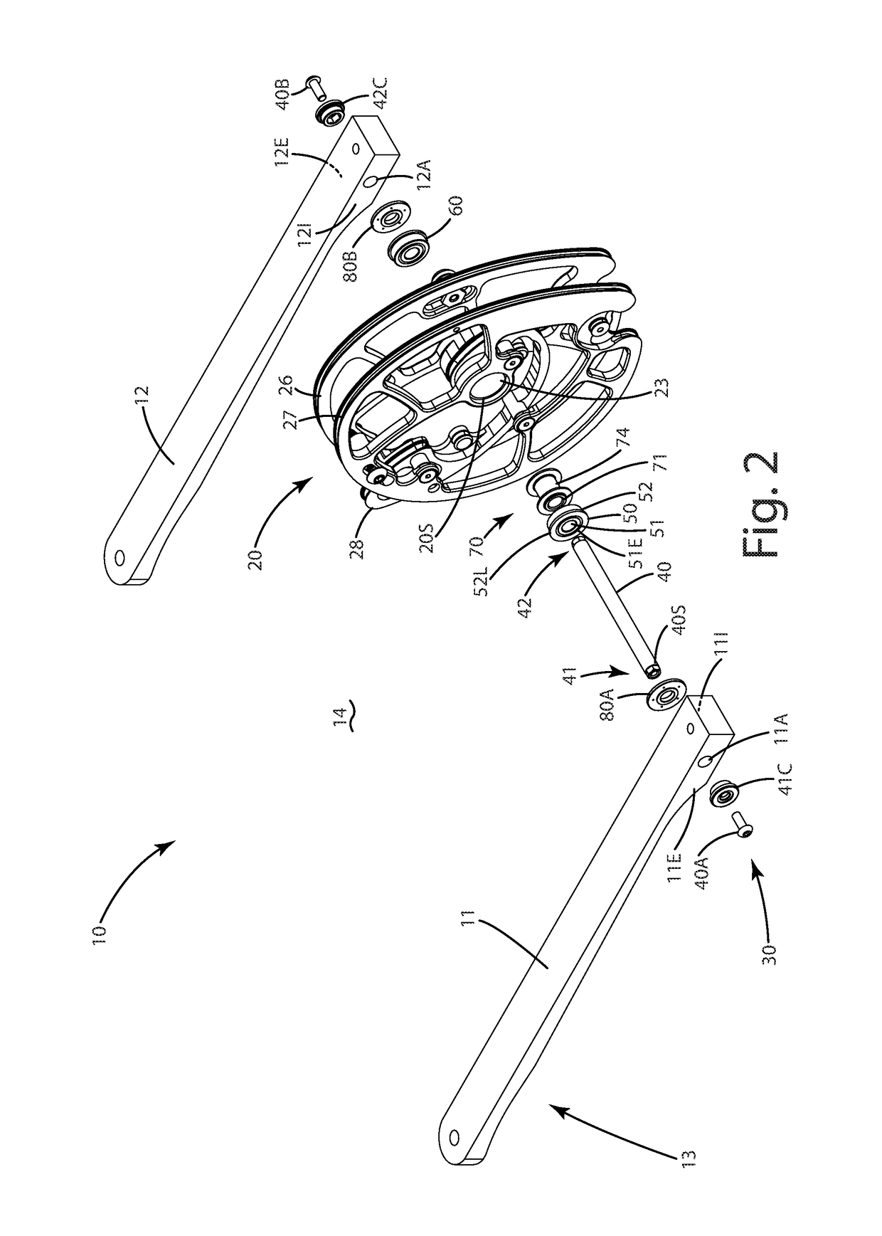
[0025]A compound archery bow including one or more cams and an axle system in accordance with a current embodiment is illustrated in FIGS. 1-4 and generally designated 10. The bow can include a cam 20, which optionally is part of a dual cam system on the bow 10. The cam can include a one or more tracks 26, 27, 28, which can be bowstring tracks, a power cable track or other tracks suitable to receive and guide elongated elements such bowstrings and power cables. An example of such a cam is disclosed in U.S. Pat. No. 9,453,698 to Grace, which is hereby incorporated by reference in its entirety.

[0026]The cam 20 can be mounted to a limb 13, which can be joined with the riser 15 of the bow. The exemplary cam 20 illustrated can be an upper cam, and the bow can include another lower cam (not shown) spaced apart from the upper cam and of a similar configuration. The limb 13 can be in the form of a split limb, including first sub limb or limb portion 11 and a second sub limb or limb portion ...


PUM


Abstract

An archery bow is provided including an axle assembly that compresses bearing and other components between limb portions to clamp those components against one another, with zero gaps therebetween, yet enable a cam to freely rotate relative to the axle. The bow can include bearings having an inner portion, and an outer portion non-rotatably joined with a cam. A fastener is operable in a compression mode to exert a compression force, such as an axial clamping force, against the bearing inner portion so it is non-rotatable relative to the axle, while the outer portion remains uncompressed and rotatable relative to the axle. The assembly can include a compression spacer clamped under the compression force between inner portions of bearings. These constructions can enhance the consistency of cam rotation and promote a smooth draw of the bow. Related methods are also provided.

Description

BACKGROUND OF THE INVENTION[0001]The present invention relates to archery products, and more particularly to an axle assembly for a cam on an archery bow.[0002]Conventional compound and crossbow archery bows include a bowstring and a set of power cables that transfer energy from the limbs and cams, eccentrics or pulleys (which are all referred to generally as “cams” herein) of the bow to the bowstring, and thus to an arrow shot from the bow. The function of the cams is to provide a mechanical advantage so that energy imparted to the arrow is a multiple of that required of an archer to draw the bow. The cams typically are rotatably mounted to limbs via respective axles.[0003]Generally, there are two primary types of limb systems for archery bows. Some bows include solid limbs that define recesses configured to receive cams near the free ends of the solid limbs. The remainder of the solid limbs, from the recess to the riser, is solid and one piece. Other bows include split limbs, whic...

Claims


Application Information

Patent Timeline
IPC IPC(8): F41B5/10F41B5/12
CPCF41B5/105F41B5/123
Inventor GRACE, NATHANIEL E.PRATER, SCOTT C.CHURCH, RAYOMEN E.
Owner GRACE ENG
Why Eureka
Try Eureka