A high temperature gas spiral purification device

A purification device and high-temperature gas technology, applied in chemical instruments and methods, dispersed particle separation, separation methods, etc., can solve the problem of inability to meet resource recycling and environmental protection, energy-saving and high-efficiency development, inability to adapt to high-temperature gas purification occasions, high-temperature gas can not directly To achieve the effect of enhanced separation effect and efficiency, excellent purification and separation effect, stable and reliable working performance

Inactive Publication Date: 2017-08-25
SIPING CITY DONGSHENG HEAT EXCHANGER MFG CO LTD
View PDF5 Cites 0 Cited by
  • Summary
  • Abstract
  • Description
  • Claims
  • Application Information

AI Technical Summary

Problems solved by technology

Although the two types of separators are used in different occasions, they have a common disadvantage: because there is no barrier between the air inlet and the outlet channel, when the pressure and flow rate fluctuate, there will be an airflow, which will cause a short circuit of the airflow and promote a considerable part of the airflow. The solid particles are carried away by the air flow, resulting in a significant decrease in the separation effect
And a single device cannot separate all solid particles with different particle sizes and qualities
Not only that, but the equipment can only be used for the purification and separation of normal-temperature gas, and cannot adapt to high-temperature gas purification occasions, nor can it separate high-temperature particles below 1.0 μm, so that the high-temperature gas purified by it cannot be directly used, and cannot meet the needs of resource regeneration and utilization. Special needs for environmental protection, energy saving and efficient development

Method used


Image

  • A high temperature gas spiral purification device
  • A high temperature gas spiral purification device
  • A high temperature gas spiral purification device

Examples


Embodiment Construction

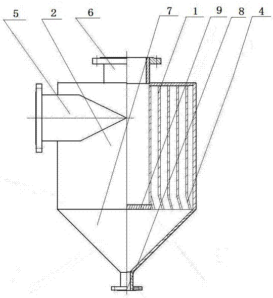
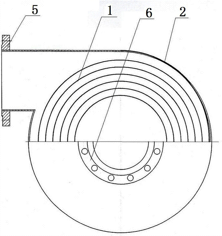
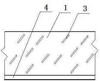
[0010] Figure 1-Figure 3 The high-temperature gas spiral purification device shown in the present invention is a novel spiral purification device designed on the basis of the prior art. Its middle part is the spiral purification main body 2 that is made of spiral plate 1, and described spiral plate 1 is on the inner plate surface, is provided with several slat-shaped collision protrusions 3 with the same inclination angle, and the collision protrusions 3. Arrange and combine according to the quincunx shape and distribute evenly in the horizontal direction. At the same time, the bottom plate part is set as an anti-flooding chamfer 4 inclined to the outside. The inclination angle, length and width of the collision protrusion 3, the inclination angle and height of the anti-flooding chamfer 4 and the size of the blanking gap can be determined according to the actual situation. In general, the inclination angle of the collision protrusion 3 is 40-45° and the inclination angle of ...


PUM


Abstract

The invention discloses a spiral purification device for high-temperature gas. According to the device, a plurality of lath-shaped collision bulges which have the same inclination angles and are arranged in a quincunx shape are arranged on inner side plate surfaces of a spiral plate forming a spiral purification body, a bottom plate part is arranged to be a flooding-preventing chamber inclined outwards, and a flooding blocking plate for isolating a material falling bin and an exhaust port is arranged at the top of the material falling bin corresponding to the exhaust port. Part of larger particles and microparticles collide gathered large particles and are separated under triple actions of centrifugal force, self-gravity and inertia force; pulling of uprising airflow to falling particles is eliminated, airflow shortcircuit and flooding of the particles in the material falling bin are prevented, and the particles rapidly slide off. The separation and purification effects are remarkable, and the spiral purification device further has the advantages of novel and unique concept, compact and reasonable structural design, stable and reliable working performance, excellent purification and separation effects and capability of reducing atmosphere dust emission, creating environment beneficial to health of human beings and increasing energy recycling and the like; compared with the prior art, the spiral purification device has prominent substantive features and remarkable progress.

Description

technical field [0001] The invention relates to a high-temperature gas purification equipment, in particular to a high-temperature gas purification equipment capable of effectively removing solid particles in a high-temperature gas below 600°C so that the gas can be purified and reused as dry gas or directly discharged. Background technique [0002] Separation of solid particles from gas is generally carried out by gravity separation, centrifugal separation, washing separation, filtration separation, electrostatic separation and magnetic separation. Due to the device of gravity separation and centrifugal separation, its structure is simple, its performance is reliable, and its application range is wide, so it is widely used in the industrial field. According to the structure, it is mainly divided into two categories. One type is a cyclone separator with centrifugal separation as the main part and gravity separation as the auxiliary part; the other type is the gravity separa...

Claims


Application Information

Patent Timeline
Patent Type & Authority Patents(China)
IPC IPC(8): B01D45/08B01D45/02B01D45/12
CPCB01D45/02B01D45/08B01D45/12
Inventor 姜万臣赵兴华刘翠华
Owner SIPING CITY DONGSHENG HEAT EXCHANGER MFG CO LTD
Why Eureka
Try Eureka