
Patellar ligament spacer for ACL injuries

a technology of patellar ligament and spacer, which is applied in the field of patellar ligament spacer for acl injuries, can solve the problems of arthrosis of the joint, frequent failure, and unsatisfactory long-term performance, and achieves minimal invasive stabilization of the knee joint, stable the knee joint, and low friction

Active Publication Date: 2018-11-20
KYON
View PDF39 Cites 1 Cited by
  • Summary
  • Abstract
  • Description
  • Claims
  • Application Information

AI Technical Summary

Benefits of technology

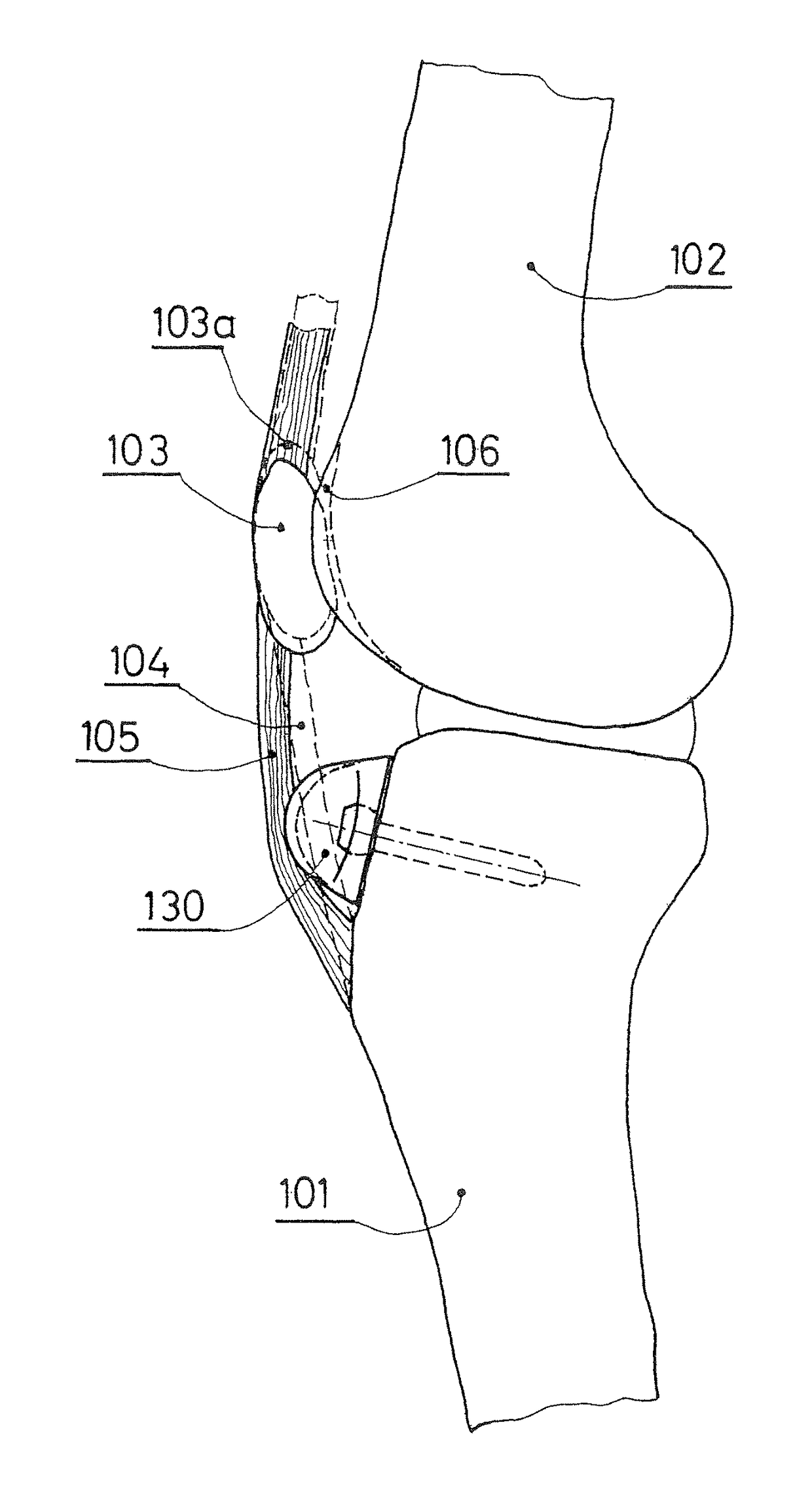
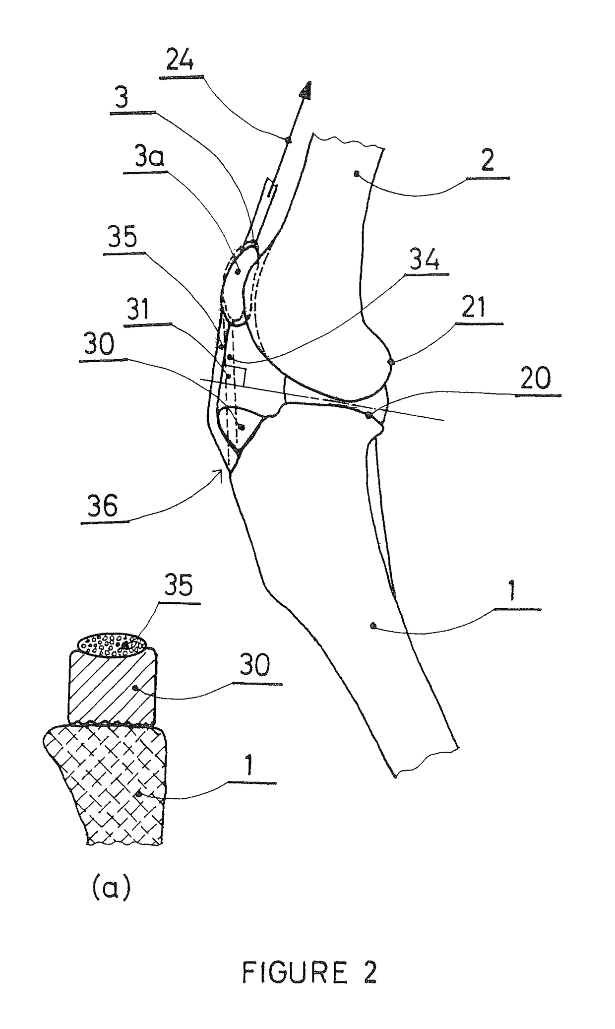
[0010]This invention provides a solution for a minimally invasive stabilization of a knee joint, in dog and in human, by cranially (anteriorly) advancing the patellar ligament just proximally to its insertion to the tibia. According to one aspect of the invention, a spacer is configured to be placed between the distal section of the patellar ligament and the tibia. The spacer is sized and shaped to alter the orientation of the patellar ligament by a pre determined amount. The alteration stabilizes the knee joint which has been weakened by an ACL (or CrCL) failure. According to another aspect of the invention, the spacer may be made from an artificial material, e.g. metal (titanium, stainless steel or a cobalt chromium alloy) or polymer (PEEK, UHMWPE), or from bone (autograft or allograft). According to another aspect of the invention, the spacer is fixed to the tibia body by either conventional screw(s) or an anchor screw, similar to those used for dental implants. According to another aspect of the invention, the surface of the spacer facing the patellar ligament is smooth and exhibits low friction. The material for the spacer should be biocompatible and resistant to wear.

Problems solved by technology

It also frequently fails, particularly in dogs, after, a degenerative process of still unknown etiology.
The procedure results in a stable knee, but the long-term performance is often unsatisfactory—75 to 90% of cases result in arthrosis of the joint within 15 years of the procedure.
However, the extra capsular suture technique regularly results in failure.
These are significantly invasive procedures which change the overall geometry of the stifle.
Nevertheless, complications and progressing arthrosis are common with each of these techniques.
Again, they require significantly invasive procedures to insert them within the stifle.
Even then, they generally end up in failure.

Method used


Image

  • Patellar ligament spacer for ACL injuries
  • Patellar ligament spacer for ACL injuries
  • Patellar ligament spacer for ACL injuries

Examples


Embodiment Construction

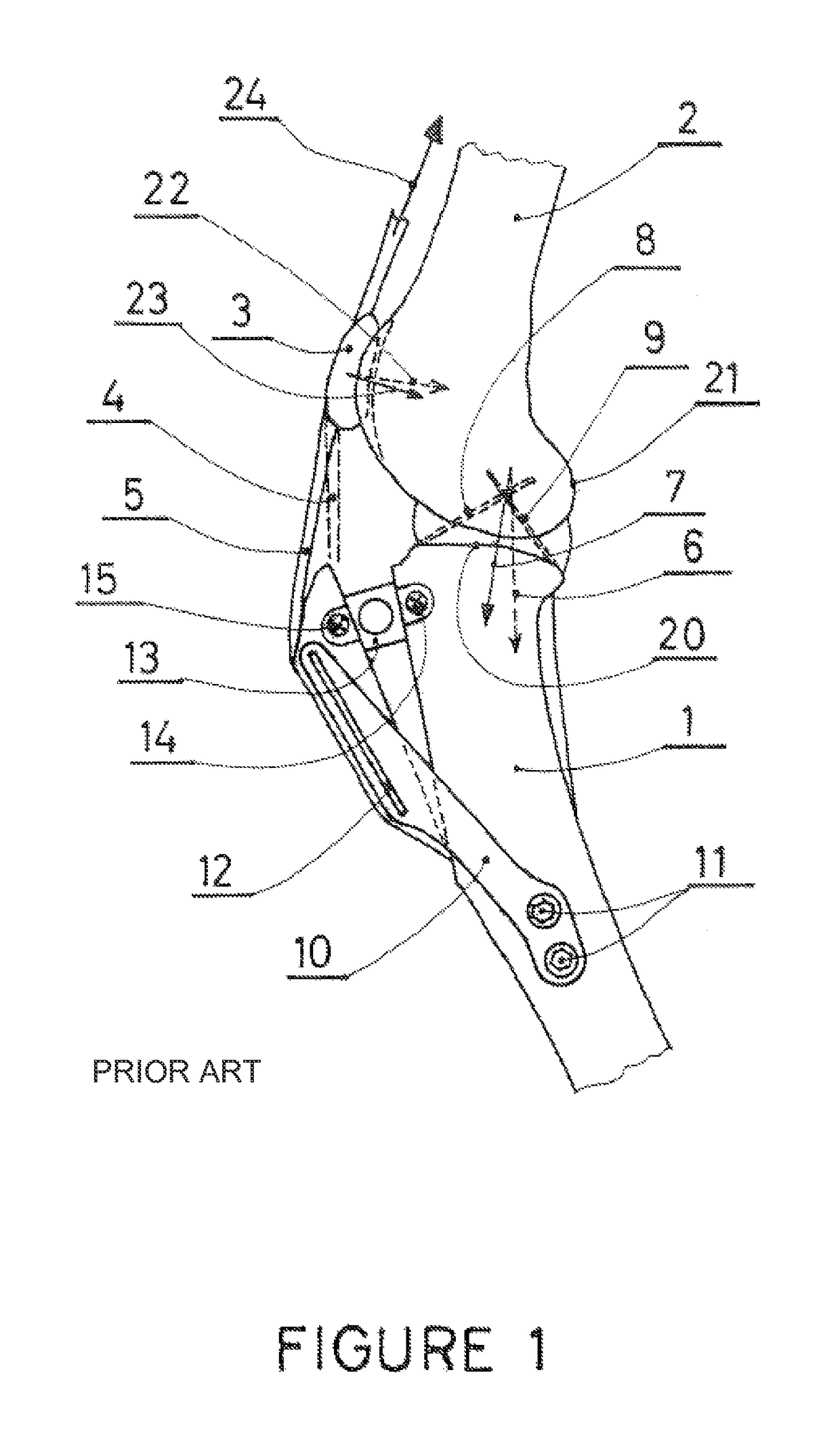
[0020]The present invention provides a spacer and a procedure for adjusting the position and angle of the patellar ligament in order to stabilize the knee. The knee is stabilized through geometric changes similar to those achieved by TTA in a much less invasive procedure. The TTA procedure is explained in connection with FIG. 1 to illustrate stabilization of the knee. The TTA procedure is currently accepted as a standard treatment for ruptured ACL in dogs (Fossum T W, Small Animal Surgery, Elsevier Health Sciences, 3rd edition, 2007; Boudrieau R, Tibial Plateau Leveling Osteotomy Or Tibial Tuberosity Advancement?, Vet. Surg. 38:1-22, 2009). FIG. 1 illustrates the knee joint both before and after the TTA procedure. The tibia 1 and the femur 2 articulate at the knee joint via condyles of the femur 21 and condyles of the tibia, also commonly referred to as the tibial plateau 20. Pull 24 from the quadriceps muscles acts on the patella 3, which in turn pulls onto the tibia via patellar l...


PUM

PropertyMeasurementUnit
angleaaaaaaaaaa
angleaaaaaaaaaa
angleaaaaaaaaaa

Abstract

A method and implant to treat anterior cruciate ligament (ACL) injuries are disclosed. The method involves advancing the insertion of the patellar ligament to the proximal tibia. The implant includes a spacer (30) which is inserted between the patellar ligament and the tibia and fixed to the tibia. The spacer decreases the angle between the patellar ligament and the tibia plateau and consequently modifies the internal joint force, restoring stability to the joint even if the ACL is ruptured. The method and implants are applicable to both human and canine patients.

Description

CROSS REFERENCE TO RELATED APPLICATION[0001]This application is a 35 U.S.C. 371 National Phase Entry Application from PCT / EP2011 / 069957, filed Nov. 11, 2011, which claims the benefit of European Patent Application No. 10191075.0 filed on Nov. 12, 2010, the disclosure of which is incorporated herein in its entirety by reference.BACKGROUND OF THE INVENTION[0002]Field of the Invention[0003]The invention relates to a method and implants to treat a knee with an injured or ruptured anterior cruciate ligament.[0004]Discussion of Related Art[0005]The Anterior Cruciate Ligament (ACL) in the human knee joint, commonly called Cranial Cruciate Ligament (CrCL) in the canine stifle, is frequently torn in trauma. It also frequently fails, particularly in dogs, after, a degenerative process of still unknown etiology.[0006]In human orthopedics, the standard procedure calls for replacement by an ACL allograft, a part of the patient's own patellar ligament, or a part of the tendon removed from his ham...

Claims


Application Information

Patent Timeline
Patent Type & Authority Patents(United States)
IPC IPC(8): A61F2/38A61B17/56A61F2/30A61F2/08
CPCA61F2/389A61B17/56A61F2/08A61F2/3877A61F2002/30703A61F2220/0008A61F2310/00856A61F2230/0095A61F2250/0081A61F2310/00017A61F2310/00023A61F2310/00029A61F2310/0058A61F2230/0045A61F2002/307
Inventor TEPIC, SLOBODANTEPIC, INJA
Owner KYON
Learn More