Opening/closing control device of chuck

a control device and chuck technology, applied in the field of machine tools and auxiliary equipment, can solve the problems of insufficient gripping force of work, difficult to change the setup of the machine, and large load of the operator, so as to prevent the set error, facilitate and rapid data carrying, and confirm the position change of the claw

Active Publication Date: 2018-11-20
NAKAMURATOME SEIMITSU IND
View PDF25 Cites 2 Cited by
  • Summary
  • Abstract
  • Description
  • Claims
  • Application Information

AI Technical Summary

Benefits of technology

[0019]It is possible to easily and rapidly carry the data and set the data in the controller when setting up, by registering the information of the chuck to be used every product type of the work to be processed, the work gripping direction, and the stroke for opening and closing the chuck as the electronic data, it is possible to prevent the set error of the work gripping position and releasing position, it is possible to confirm the position change of the claw in the chuck during processing, and it is possible to detect abnormality in the machine.
[0020]More specifically, according to the invention, the work load when setting up can be widely lightened since the position adjustment of the sensor is not necessary, and it is possible to prevent the adjustment error and dispersion of adjustment by the worker. Further, it is possible to easily find the error in the used chuck when setting up, the error in the attaching position of the claw, and the error in the work.

Problems solved by technology

However, in the case that the claw comes into collision with something and stops before the claw grips the work, for example, due to attachment of foreign material to the work or supply of different diameter work, the work can not be gripped by the sufficient force.
As a result, a load of the operator is great, and it takes a long time to change the setup of the machines when the product type is changed.
Further, there is the danger that a defect product is generated and the tool is broken due to setting error, and the skill of the operator is necessary.

Method used


Image

  • Opening/closing control device of chuck
  • Opening/closing control device of chuck
  • Opening/closing control device of chuck

Examples


Embodiment Construction

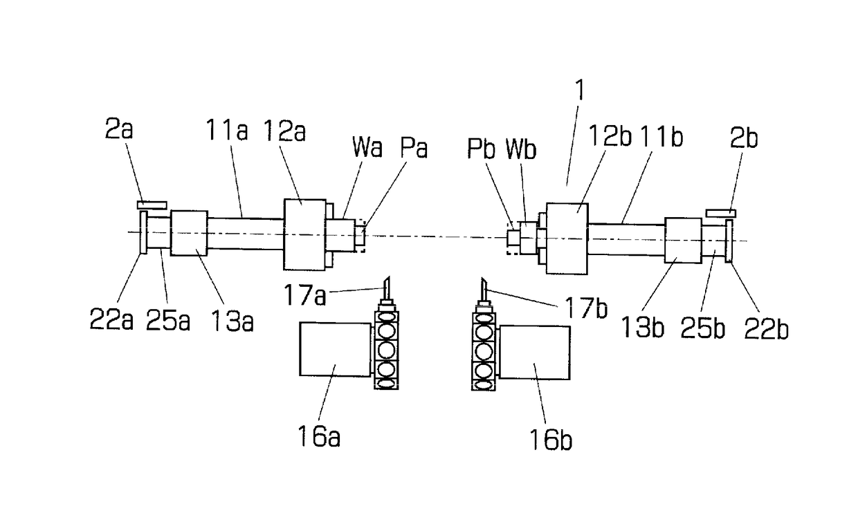
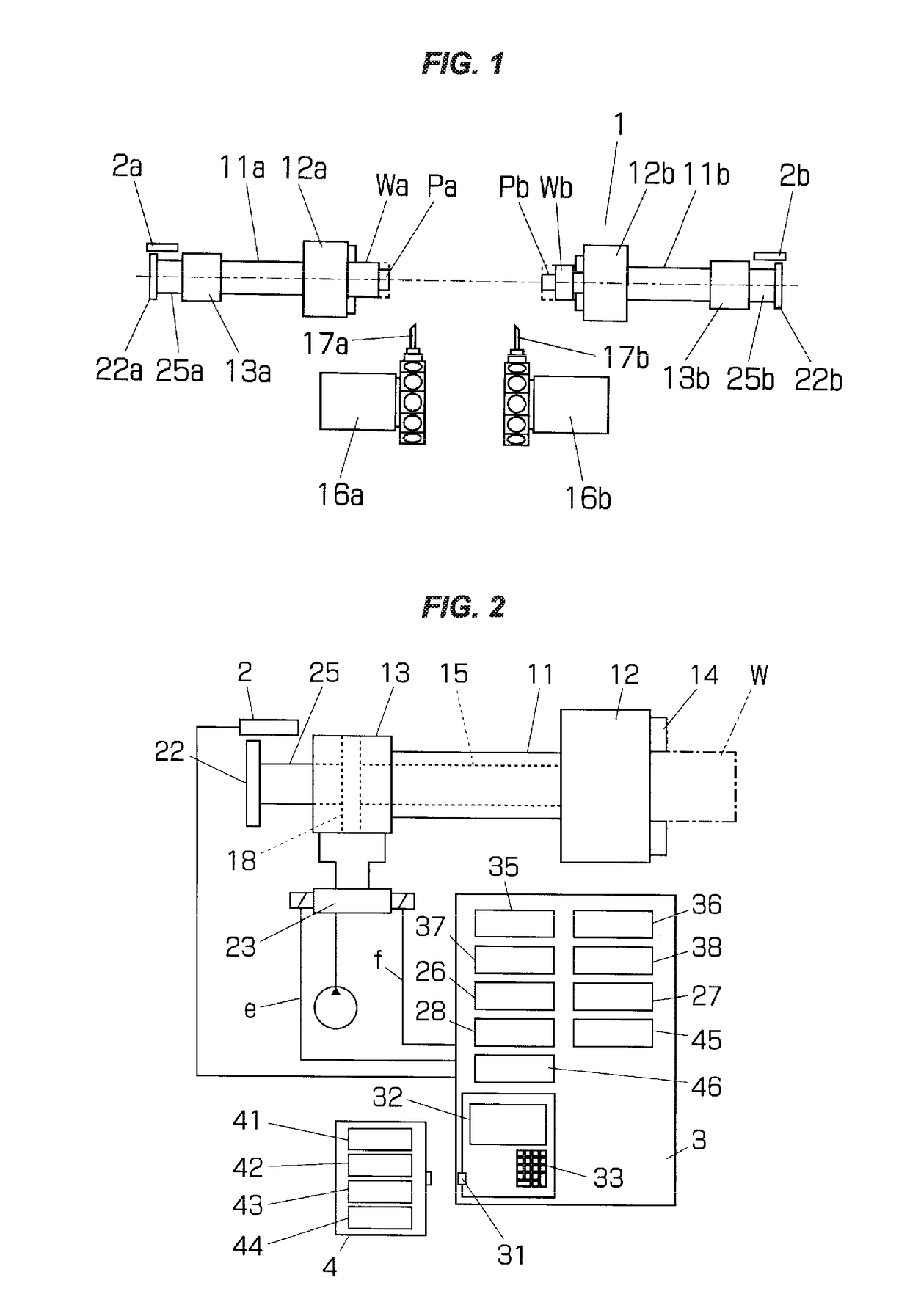
[0025]A description will be given below of an embodiment of the invention by exemplifying a two-main spindle opposed lathe turning machine. FIG. 1 is a block diagram schematically showing a machine body of the two-main spindle opposed lathe turning machine, and FIG. 2 is a block diagram showing a substantial part and a control system thereof. In the drawings, reference numeral 1 denotes a machine body, reference numeral 3 denotes a controller, and reference numeral 4 denotes an external memory device such as a USB memory.

[0026]The machine body 1 is provided with two main spindles 11 (11a, 11b) which are opposed on the same axis. A chuck 12 (12a, 12b) gripping a work W (Wa, Wb) is attached to a leading end (an opposed end) of each of the main spindles, and a chuck cylinder 13 (13a, 13b) carrying out an opening and closing motion of the chuck 12 is attached to a rear end thereof. The main spindle 11 is constructed by a hollow shaft, and is operationally coupled to each of chuck claws ...


PUM


Abstract

The invention relates to a device controlling a chuck of a machine tool and an auxiliary equipment thereof, thereby facilitating a setup work. Gripping and releasing of a work are confirmed by registering a work gripping position and a work releasing position of a chuck, a kind of a used chuck, and a gripping direction of a work in an external memory device every product type of the work, transferring the work gripping position and the work releasing position in correspondence to the product type to a controller of a machine tool displaying them on a display of an operator control panel, detecting a position of an operation rod opening and closing a claw of the chuck by a stroke sensor, referring to the gripping position of the work, and detecting conformity of the detecting position and set values of the work gripping position and the work releasing position.

Description

TECHNICAL FIELD[0001]The invention relates to a machine tool and an auxiliary equipment thereof, and more particularly to a device for controlling an opening and closing motion of a three-claw chuck and a collet chuck which grip a work forming an object to be processed.BACKGROUND ART[0002]A chuck gripping a work in a leading end of a main spindle is installed to a machine tool such as a lathe turning machine. In the automated lathe turning machine, the main spindle is constructed by a hollow shaft, and work gripping and releasing operation of the chuck is carried out by movement in an axial direction of an operation rod which is inserted into a hollow hole. A chuck cylinder moving the operation rod is attached to a rear end of the main spindle. Since a diameter of a portion which is gripped by the chuck is different according to a kind of the work (hereinafter, refer to as “product type”), a position of a claw of the chuck when gripping the work is different according to the product...

Claims


Application Information

Patent Timeline
Patent Type & Authority Patents(United States)
IPC IPC(8): B23Q17/00B23B31/30
CPCB23B31/30B23Q17/003B23B2231/10Y10T279/21B23B2260/128B23Q2717/003B23B2231/26
Inventor MIYAMOTO, TAKASHISAKAI, TOMOKIARAI, TOMONORI
Owner NAKAMURATOME SEIMITSU IND
Why Eureka
Try Eureka