Capacitive-discharge electromagnetic propulsion system

a technology of electromagnetic propulsion and capacitor, which is applied in the direction of mechanical equipment, mechanical energy handling, machines/engines, etc., can solve the problems of no longer valid assumption and no

Inactive Publication Date: 2018-11-20
PURVIS JAMES WAYNE
View PDF37 Cites 4 Cited by
  • Summary
  • Abstract
  • Description
  • Claims
  • Application Information

AI Technical Summary

Problems solved by technology

As discussed above, modern electrodynamics has shown that this is no longer a valid assumption.
Engineering exploitation of this situation, to date, has not been effected due to the “circuit completion” problem.

Method used


Image

  • Capacitive-discharge electromagnetic propulsion system
  • Capacitive-discharge electromagnetic propulsion system
  • Capacitive-discharge electromagnetic propulsion system

Examples


Embodiment Construction

[0023]The present invention will now be described more fully hereinafter with reference to the accompanying drawings, in which preferred embodiments of the invention are shown. This invention may, however, be embodied in many different forms and should not be construed as limited to the embodiments set forth herein. Rather, these embodiments are provided so that this disclosure will be thorough and complete, and will fully convey the scope of the invention to those skilled in the art. Like numbers refer to like elements throughout.

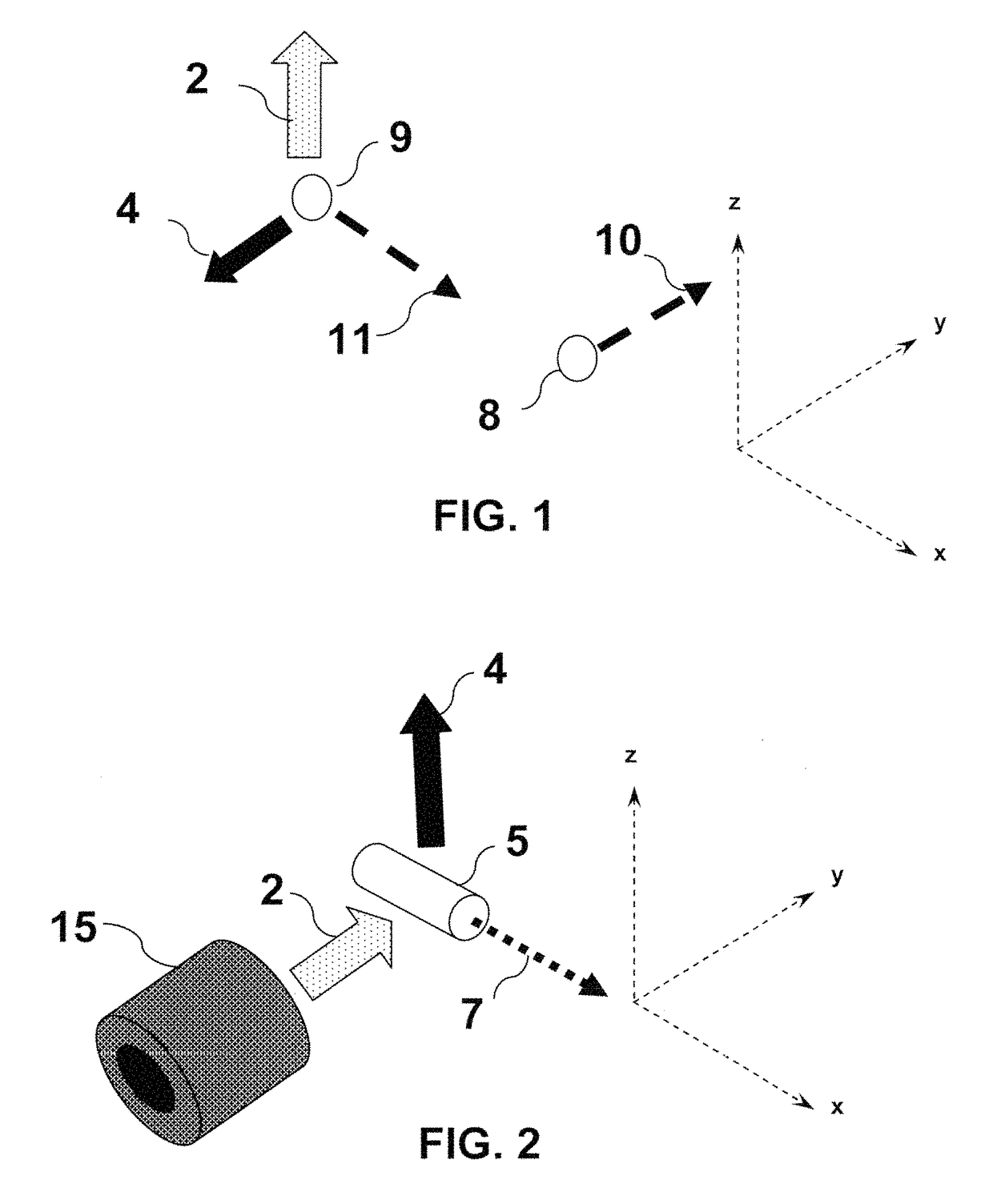
[0024]By way of further background, the situation presented in FIG. 1 is also well known to those skilled in the art and familiar with the works of Feynman. The figure illustrates two positively charged coplanar particles 8 and 9 moving with respective orthogonal velocities 10 and 11, with velocity vector 10 being parallel to the y-axis of the coordinate system shown, and velocity vector 11 being parallel to the x-axis. At the instant shown, particle 8 ind...


PUM


Abstract

The present invention discloses an apparatus and method for electromagnetic spacecraft propulsion. The apparatus includes capacitor assemblies bracketed by electromagnetic solenoids configured in Helmholtz Coil geometries. The action of magnetic fields generated in the solenoids on segmented currents in conductive discharge elements during capacitor discharge produces unidirectional forces, while reaction momentum is carried away by Poynting Vector electromagnetic fields in conformity with the currently understood principles of electrodynamics.

Description

FIELD OF THE INVENTION[0001]The present invention discloses an apparatus and method for electromagnetic spacecraft propulsion. In particular, thrust is generated without the expulsion of reaction mass. This unique system and method is comprised of capacitor assemblies with discharge elements and electromagnetic coils. A unidirectional Lorentz Force is generated by the magnetic fields from the coils acting on the segmented current in the discharge element during capacitor discharge.BACKGROUND OF THE INVENTION[0002]One of the most significant metrics for space propulsion systems is specific impulse, which is the ratio of thrust produced to the rate of propellant consumed. Specific impulse has units of seconds, and is essentially the number of seconds that a pound of propellant will produce a pound of thrust. The higher the specific impulse the less propellant mass and associated tankage required for a given space mission. The Stafford Synthesis Group (Stafford, America at the Threshol...

Claims


Application Information

Patent Timeline
Patent Type & Authority Patents(United States)
IPC IPC(8): H02K41/02F03H99/00
CPCH02K41/02H02K2207/00F03H99/00F41B6/00
Inventor PURVIS, JAMES WAYNE
Owner PURVIS JAMES WAYNE
Why Eureka
Try Eureka