Lens bracket assembly and gimbal used therewith

a technology of lens brackets and gimbals, which is applied in the field of shooting apparatuses, can solve the problems of difficult adjustment of the center of gravity, difficult relative movement, and very large friction force between the structural members, and achieve the effect of rapid adjustment to balance the center of gravity and increase the stiffness between the lens

Active Publication Date: 2018-11-20
SZ DJI OSMO TECH CO LTD
View PDF39 Cites 4 Cited by
  • Summary
  • Abstract
  • Description
  • Claims
  • Application Information

AI Technical Summary

Benefits of technology

[0005]An objective of the present invention is to provide a lens bracket assembly, and a gimbal used with the assembly, to be rapidly adjusted to balance the center of gravity and to increase stiffness between a lens and a body of an imaging device.
[0046]Compared with the prior art, a bracket of the lens bracket assembly according to the present invention is fixed onto a supporting plate, an imaging device is mounted to the supporting plate, and the bracket supports a lens of the imaging device. Therefore, stiffness between the lens and a body of the imaging device is increased. In addition, the supporting plate is slidably disposed on the mounting plate, and the pressing device locks the supporting plate with the mounting plate. Therefore, the mounting plate can be locked to any predetermined position on the supporting plate through the pressing device, which increases the locking precision of the mounting plate. Moreover, the lens bracket assembly has a small volume and is easy to assemble and disassemble. The center of gravity of the gimbal can be adjusted through the lens bracket assembly.

Problems solved by technology

However, as the existing structure of adjusting the center of gravity adjusts the center of gravity by use of relative displacement of the gimbal structure, and as most of the structural members carry load, the static friction force between the structural members is very great, causing the relative movement to be difficult.
Moreover, a small relative displacement also affects the center of gravity significantly, causing adjustment of the center of gravity to be difficult.
In addition, it is difficult to mount the existing video camera and gimbal.
The steps of mounting are more complicated.
Structural deformation is large during locking, and bad connections are resulted.
As a result, the gimbal has poor system stiffness, and it is very difficult to increase the precision.
Poor connection stiffness between some video cameras and lenses is also one of the reasons for leading to poor system stiffness of the gimbal.

Method used


Image

  • Lens bracket assembly and gimbal used therewith
  • Lens bracket assembly and gimbal used therewith
  • Lens bracket assembly and gimbal used therewith

Examples


Embodiment Construction

[0058]The technical solution in embodiments of the present invention is clearly and completely described below with reference to the accompanying drawings of the embodiments of the present invention. It is apparent that the embodiments described are merely some embodiments of the present invention instead of all the embodiments. Based on the embodiments in the present invention, all other embodiments obtained by persons of ordinary skill in the art without making creative efforts should fall within the protection scope of the present invention.

[0059]Implementation of the present invention is described below in detail in combination with specific implementation manners.

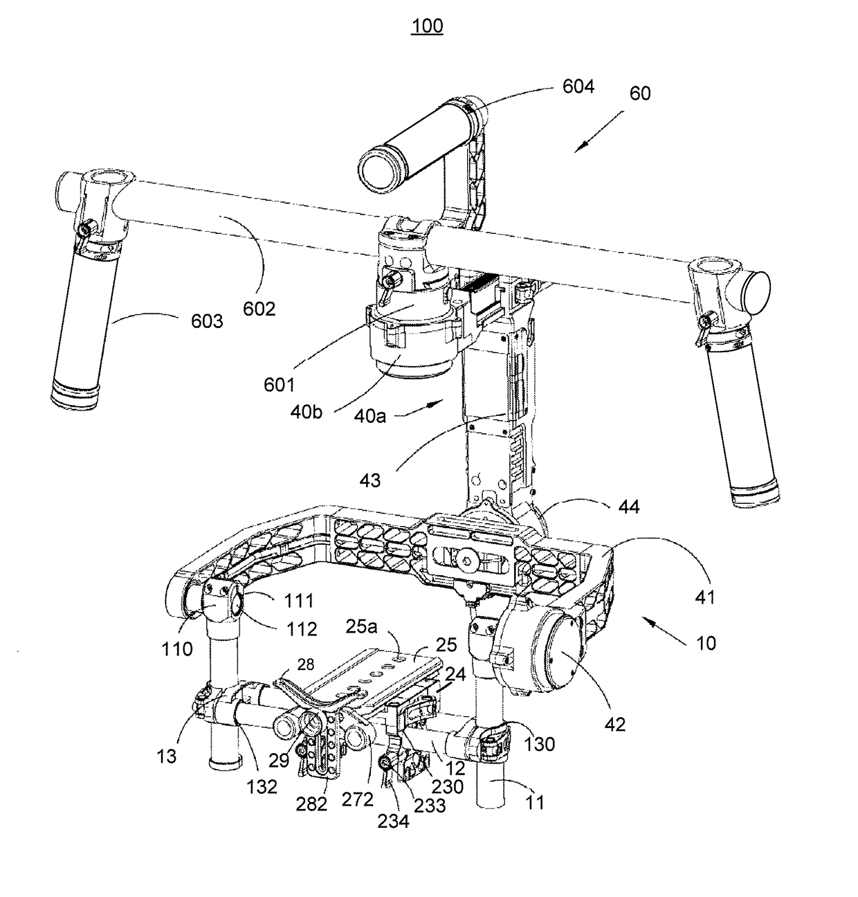
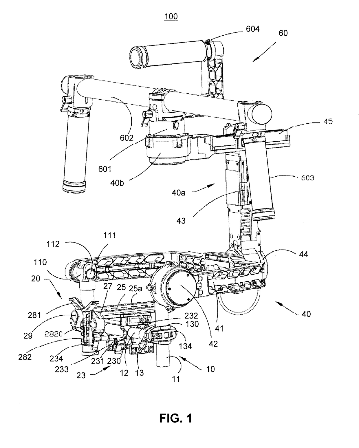
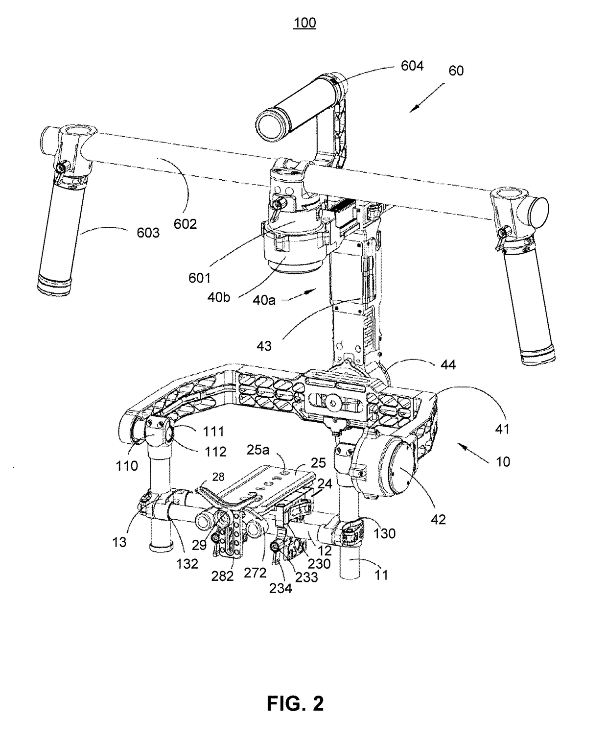
[0060]Referring to FIG. 1 to FIG. 2 together, a gimbal 100 according to the present invention is used for carrying an imaging device 200 (as shown in FIG. 9). The imaging device 200 may be a camera, a video camera, a lens or the like. In this embodiment, the imaging device 200 is a camera, which includes a body 201 and...


PUM


Abstract

The present invention discloses a lens bracket assembly for supporting an imaging device. The imaging device includes a body and a lens connected to the body. The lens bracket assembly includes a supporting plate and a bracket. The supporting plate is used for mounting the imaging device, and the supporting plate includes a first side. The bracket includes a supporting portion of which the shape matches the lens of the imaging device and a fixing portion connected with the supporting portion. The fixing portion is fixedly arranged at the first side. The supporting portion is used for supporting the lens. The present invention further relates to a gimbal that uses the lens bracket assembly.

Description

CROSS-REFERENCE TO RELATED APPLICATIONS[0001]This application is a continuation application of International Application No. PCT / CN2014 / 081046 filed on Jun. 27, 2014, the content of which is hereby incorporated by reference in its entirety.BACKGROUND OF THE INVENTION[0002]The present invention relates to the field of shooting apparatuses, and in particular, to a lens bracket assembly and a gimbal used therewith.[0003]A gimbal is used for mounting a supporting worktable used by a video camera, the video camera being disposed on the gimbal. By adjusting the gimbal, the lens of the video camera is adjusted to achieve correct photographing of targets. The gimbal is compatible with lots of different types of video cameras or lenses, and the center of gravity of each axis of the gimbal is adjustable. However, as the existing structure of adjusting the center of gravity adjusts the center of gravity by use of relative displacement of the gimbal structure, and as most of the structural memb...

Claims


Application Information

Patent Timeline
Patent Type & Authority Patents(United States)
IPC IPC(8): H04N5/225F16M11/12F16M11/20F16M11/18F16M11/04G03B17/56
CPCH04N5/2253F16M11/04F16M11/123F16M11/18H04N5/2254G03B17/563G03B17/566H04N5/2251F16M11/2035H04N23/55F16M11/041F16M11/048F16M11/2057F16M11/2085F16M13/04H04N23/54
Inventor PAN, PAULZHAO, XI FENGZHAO, YAN CHONG
Owner SZ DJI OSMO TECH CO LTD
Why Eureka
Try Eureka