Charge pump and operating method thereof

Active Publication Date: 2018-11-27
RAYDIUM SEMICON
View PDF3 Cites 0 Cited by
  • Summary
  • Abstract
  • Description
  • Claims
  • Application Information

AI Technical Summary

Benefits of technology

The charge pump and operating method described in this patent only require ten switches and three capacitors to achieve a negative output voltage that is half of the input voltage in one mode and a negative output voltage that is three-fourths of the input voltage in another mode. The charge pump also operates using a "ping-pong" method to achieve the best charge transfer. This invention simplifies the design of charge pumps and reduces the number of components needed.

Problems solved by technology

Therefore, the conventional charge pump cannot achieve the best charge transfer and needed to be improved.

Method used


Image

  • Charge pump and operating method thereof
  • Charge pump and operating method thereof
  • Charge pump and operating method thereof

Examples


Embodiment Construction

[0030]A preferred embodiment of the disclosure is a charge pump. In this embodiment, the charge pump can be applied to a source driver of an OLED display panel (e.g., AMOLED display panel) for receiving an input voltage and provides an output voltage to a loading capacitor, but not limited to this.

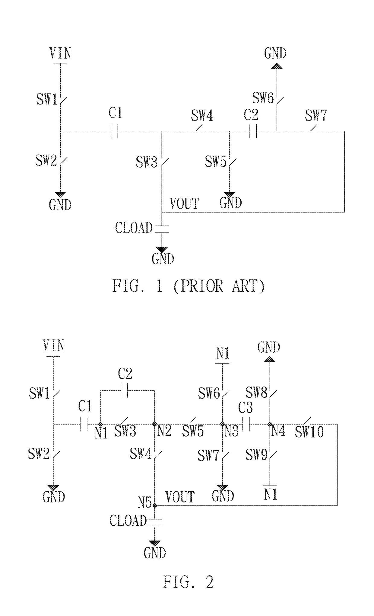
[0031]Please refer to FIG. 2. FIG. 2 illustrates a schematic diagram of the charge pump in this embodiment. As shown in FIG. 2, the charge pump in this embodiment, formed by ten switches and three capacitors, includes a first capacitor C1, a second capacitor C2, a third capacitor C3, a first switch SW1, a second switch SW2, a third switch SW3, a fourth switch SW4, a fifth switch SW5, a sixth switch SW6, a seventh switch SW7, an eighth switch SW8, a ninth switch SW9 and a tenth switch SW10.

[0032]The first switch SW1 and the second switch SW2 are coupled in series between the input voltage VIN and a ground terminal GNF. One terminal of the first capacitor C1 is coupled between the first swit...


PUM


Abstract

A charge pump and operating method thereof are disclosed. The charge pump includes a first capacitor to a third capacitor and a first switch to a tenth switch. The charge pump is used to receive an input voltage and provide an output voltage to a load capacitor. When the charge pump is operated in a first mode, the charge pump controls the second capacitor failure, the output voltage and the input voltage have opposite electricity and the output voltage is (−½) times the input voltage. When the charge pump is operated in a second mode, the charge pump controls the second capacitor failure, the output voltage and the input voltage have opposite electricity and the output voltage is (−⅔) times the input voltage.

Description

CROSS-REFERENCE TO RELATED APPLICATIONS[0001]This Application claims the benefit of U.S. Provisional Application 62 / 454,129 filed on Feb. 3, 2017.BACKGROUND[0002]Field[0003]This disclosure relates to a display panel; in particular, to a charge pump applied to an organic light-emitting diode (OLED) display panel and an operating method thereof.[0004]Description of the Related Art[0005]In the conventional OLED display panel (e.g., AMOLED display panel), the charge pump is usually disposed in the source driver. The charge pump is a DC-DC converter using the capacitor to store power and used for generating the output voltage higher than the input voltage or generating negative output voltage.[0006]As shown in FIG. 1, the conventional charge pump can include capacitors C1˜C2 and switches SW1˜SW7. Although the conventional charge pump can provide the output voltage VOUT which is (−½) times the input voltage VIN to the loading capacitor CLOAD through the operations of the capacitors C1˜C2 ...

Claims


Application Information

Patent Timeline
IPC IPC(8): H02M3/07G09G3/3208
CPCH02M3/07G09G3/3208G09G2330/02G09G2330/023G09G2330/028
Inventor CHEN, LI-CHIEHCHIEN, HSUAN-HAOHUNG, CHIH-JEN
Owner RAYDIUM SEMICON
Why Eureka
Try Eureka