Supercharge Your Innovation With Domain-Expert AI Agents!

Waterproof connector

a technology of connectors and connectors, applied in the direction of couplings/cases, coupling device connections, electrical devices, etc., can solve the problems of reducing affecting the service life of the connector, so as to achieve the effect of fewer types of components and simplified structur

Active Publication Date: 2018-11-27
SUMITOMO WIRING SYST LTD
View PDF1 Cites 1 Cited by
  • Summary
  • Abstract
  • Description
  • Claims
  • Application Information

AI Technical Summary

Benefits of technology

The patent text describes a connector assembly that has a guiding surface to help a terminal fitting smoothly enter a seal hole. The guiding surface is provided along the entire length of the through hole, and it helps prevent damage to the seal and ensures reliable waterproofness. The guiding surface can be formed by two parallel sides or an obliquely arranged axis center. Multiple rear holders can be used, and they act with each other via ribs on the connector housing, simplifying the structure and reducing the number of parts needed.

Problems solved by technology

A terminal that is inserted into the guiding tube without being guided by the taper may damage the one-piece rubber plug, and a damaged one-piece rubber plug may not ensure predetermined waterproofness.
Damage of the one-piece rubber plug is particularly notable when a center of the tab of the terminal does not coincide with a center of a box portion and is eccentric.

Method used


Image

  • Waterproof connector
  • Waterproof connector
  • Waterproof connector

Examples


first embodiment

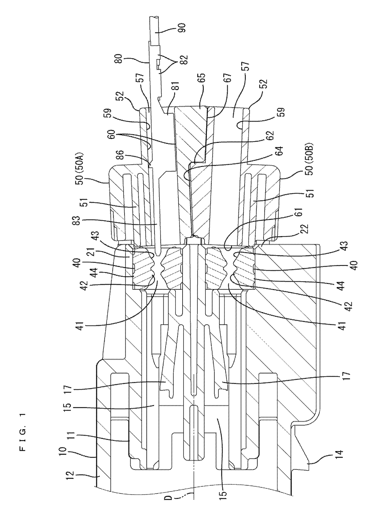
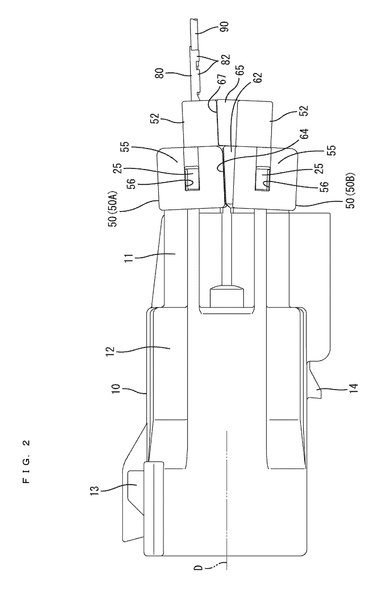
[0024]the present invention is described with reference to FIGS. 1 to 11. A waterproof connector of the first embodiment includes, as shown in FIG. 1, a connector housing 10, seal members 40 disposed in the connector housing 10, rear holders 50 disposed on the connector housing 10 for restricting the detachment of the seal members 40 from the connector housing 10, and terminal fittings 80 to be accommodated into the connector housing 10. The connector housing 10 is connectable to an unillustrated mating connector housing. Note that, in the following description, a surface side of the connector housing 10 facing the mating connector housing when connection is started (right side of FIGS. 1 and 2) is referred to as a front side concerning a front-rear direction, and a vertical direction is based on each figure except FIG. 11.

[0025]The connector housing 10 is made of synthetic resin and includes, as shown in FIGS. 5 and 6, a housing body 11 substantially in the form of a rectangular bl...

second embodiment

[0066]FIGS. 12 and 13 show the present invention. The second embodiment differs from the first embodiment in some ribs, but the other configuration is the same as in the first embodiment. Thus, the same components are denoted by the same reference signs as in the first embodiment below.

[0067]A rear holder 50 of the second embodiment is formed by omitting the second ribs 65 from the rear holder 50 of the first embodiment. Specifically, the second ribs 65 are not provided on a projecting portion 52 and only first ribs 62 are provided on a holder body 51.

[0068]In the case of the second embodiment, although an assembled state is not shown, first contact surfaces 64 of the respective first ribs 62 on the upper rear holder 50A come into contact with the upper surface of the holder body 51 in the lower rear holder 50B along the front-rear direction and first contact surfaces 64 of the respective first ribs 62 on the lower rear holder 50B come into contact with the lower surface of the hold...


PUM


Abstract

Seals 40 are disposed in a rear part of a connector housing 10, and rearward detachment of the seals 40 is restricted by rear holders 50. A terminal fitting 80 is inserted into a cavity 15 of the connector housing 10 from a through hole 57 of the rear holder 50 via a seal hole 41 of the seal member 40. The through hole 57 of the rear holder 50 is provided with a guiding surface 59 inclined toward a center of the seal hole 41 with respect to a front-rear direction toward front in a range extending substantially over the entire length of the through hole 57 in the front-rear direction with the rear holder 50 disposed on the connector housing 10.

Description

BACKGROUNDField of the Invention[0001]The invention relates to a waterproof connector.Description of the Related Art[0002]U.S. Patent Application Pub. No. 2007 / 0099501 discloses a waterproof connector with a housing body having terminal insertion openings, terminals with wire to be inserted into the terminal insertion openings, a one-piece rubber plug having wire insertion holes and a rear holder having guiding tubes. The one-piece rubber plug is accommodated into a plug accommodating portion in a rear part of the housing body and is held by the rear holder to restrict rearward detachment. The terminal is inserted into the terminal insertion opening from the guiding tube via the wire insertion hole and includes a tab on a tip. A taper is provided on one circumferential part near the rear entrance of the guiding tube. The taper is intended to guide the tab of the terminal into the guiding tube so that the tip of the tab will not will not damage the inner surface of the wire insertion...

Claims


Application Information

Patent Timeline
Patent Type & Authority Patents(United States)
IPC IPC(8): H01R13/52
CPCH01R13/521H01R13/502H01R13/5205H01R13/4223
Inventor KITAGAWA, YUJI
Owner SUMITOMO WIRING SYST LTD
Features
  • R&D
  • Intellectual Property
  • Life Sciences
  • Materials
  • Tech Scout
  • Unparalleled Data Quality
  • Higher Quality Content
  • 60% Fewer Hallucinations
Learn More