
Bar unloading apparatus of the revolver type provided with braking device

a technology of braking device and unloading apparatus, which is applied in the direction of metal-working feeding device, metal-working storage device, positioning device, etc., can solve the problem of rather low material arrival speed, and achieve the effect of speeding up the production cycle and high bar arrival speed

Active Publication Date: 2018-12-11
DANIELI & C OFF MEC SPA
View PDF5 Cites 0 Cited by
  • Summary
  • Abstract
  • Description
  • Claims
  • Application Information

AI Technical Summary

Benefits of technology

[0009]It is a further object of the present invention to provide a longitudinal bar unloading device which permits to speed up the production cycle significantly.
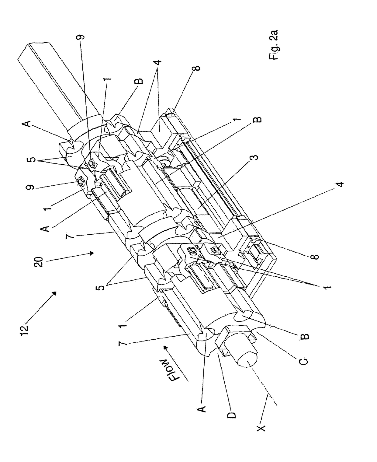
[0015]The present invention thus provides a bar unloading apparatus provided with a least one bar braking device which, by being fixed to the revolver or rotor, can rotate together with the rotor itself, thus being able to brake the bar during the rotation.
[0018]Due to the braking device of the unloading apparatus, which is the subject of the invention, the production cycle can be speeded up because the rotor can rotate as soon as the tail of the bar also enters into the respective channel, without needing to wait for the bar to be braked and for the brake to reopen so as to not hinder the rotation as occurs in the prior art. The dependent claims describe preferred embodiments of the invention.

Problems solved by technology

Therefore, these systems are only suitable for rather low material arrival speeds: the need to have an immediately free channel for the introduction of the material becomes more and more important as the speed increases.

Method used


Image

  • Bar unloading apparatus of the revolver type provided with braking device
  • Bar unloading apparatus of the revolver type provided with braking device
  • Bar unloading apparatus of the revolver type provided with braking device

Examples


Embodiment Construction

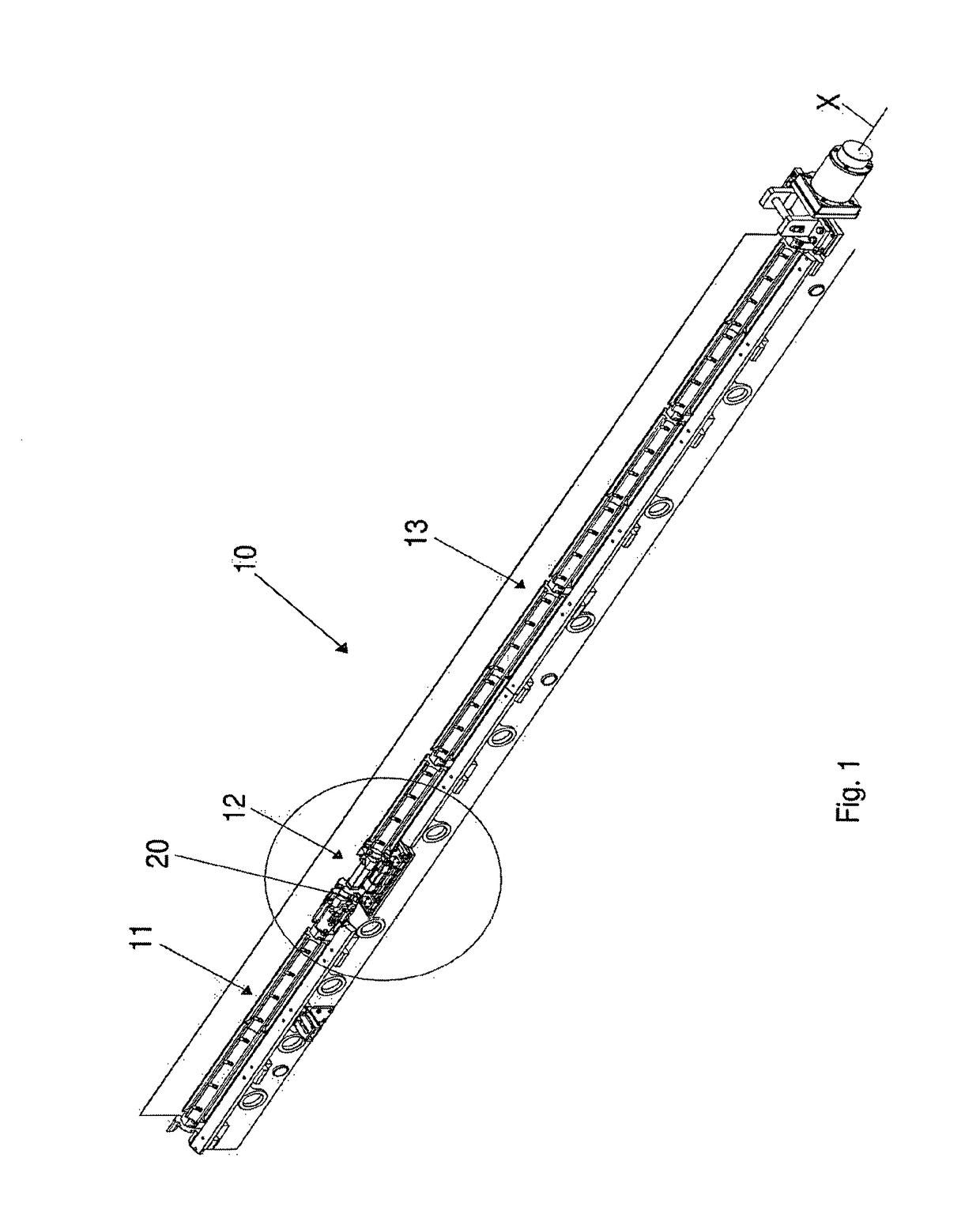
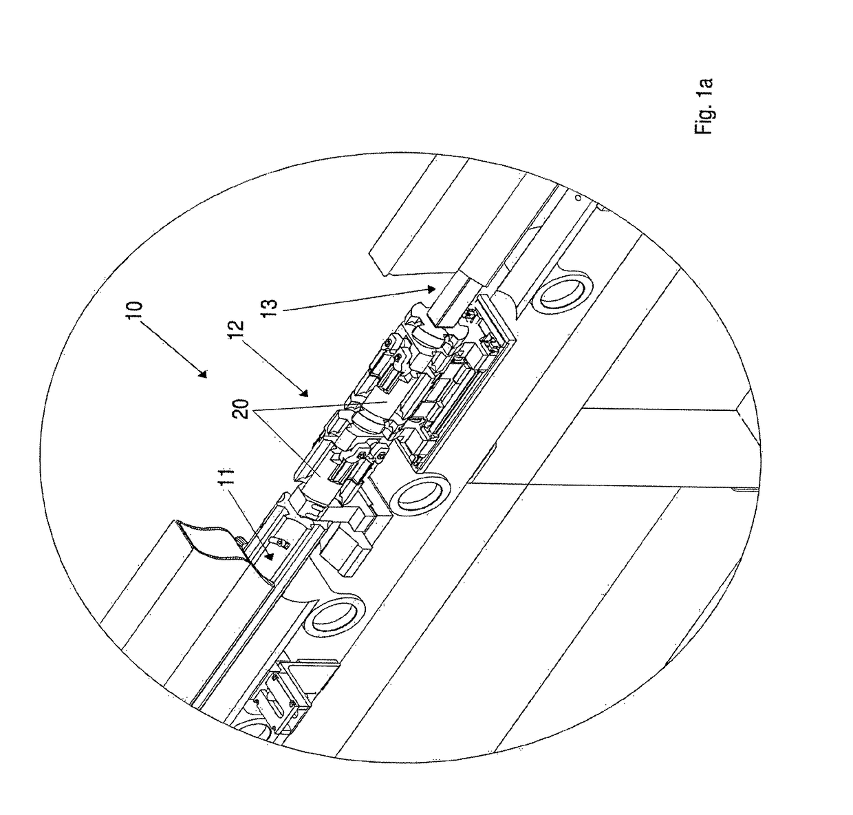
[0028]The figures show a first embodiment of an unloading apparatus adapted to receive bars at high forward speed, which bars are from an upstream plant, to brake said bars and finally unload said bars transversely from either one or the other side with respect to a vertical plane containing a longitudinal axis X defined by the apparatus itself.

[0029]The apparatus, which is the subject of the present invention, comprises:[0030]a longitudinal rotor 10 divided into at least three longitudinal stretches 11, 12, 13 integral with one another and adapted to rotate about the longitudinal rotation axis X, on the outer surfaces of which there is provided a plurality of longitudinal channels A, B, C, D, extending on the three stretches 11, 12, 13 over the whole longitudinal extension of rotor 10 and parallel to the longitudinal axis X, to receive respective longitudinal bars,[0031]and at least one braking device 20 for braking the longitudinal bars entering in at least one of the longitudinal...


PUM

PropertyMeasurementUnit
V-shapeaaaaaaaaaa
timeaaaaaaaaaa
speedaaaaaaaaaa

Abstract

A bar unloading apparatus of the revolver type, comprising: —a longitudinal rotor (10) divided into at least three longitudinal stretches (11, 12, 13) integral with one another and adapted to rotate about a longitudinal rotation axis, on the outer longitudinal surfaces of which there is provided a plurality of longitudinal channels, extending on the at least three stretches over the whole longitudinal extension of the rotor (10) and parallel to said longitudinal axis, to receive respective longitudinal bars, —and at least one braking device for braking the longitudinal bars entering in at least one of the longitudinal channels, wherein the at least one braking device is integrated in at least one first stretch (12) of said at least three longitudinal stretches (11, 12, 13), is rotationally fixed to the longitudinal rotor (10) and is provided with braking elements (1) in each of said longitudinal channels so that said at least one braking device can rotate together with the longitudinal rotor (10) and brake the longitudinal bars even during a rotation of the longitudinal rotor (10).

Description

CROSS REFERENCE TO RELATED APPLICATIONS[0001]The present application claims priority to PCT International Application No. PCT / IB2014 / 067406 filed on Dec. 30, 2014, which application claims priority to Italian Patent Application No. MI2014A000003 filed Jan. 2, 2014, the entirety of the disclosures of which are expressly incorporated herein by reference.STATEMENT RE: FEDERALLY SPONSORED RESEARCH / DEVELOPMENT[0002]Not Applicable.FIELD OF THE INVENTION[0003]The present invention relates to an unloading apparatus of the revolver type in which the bars are braked before being unloaded.BACKGROUND ART[0004]In a longitudinal bar unloading apparatus, the bars arrive at a given speed in the longitudinal direction and must be braked to unload them transversely either rightwards or leftwards.[0005]The unloading apparatuses of the revolver type are characterized by a plurality of channels or grooves or niches made on a rotor, in which the bars enter and are braked to then be rotated together with ...

Claims


Application Information

Patent Timeline
Patent Type & Authority Patents(United States)
IPC IPC(8): B21B39/08B21B43/00B21D43/00
CPCB21B39/086B21D43/006B21B43/003B21B39/08
Inventor MENOSSO, FAUSTODELLA ROSSA, FLAVIO
Owner DANIELI & C OFF MEC SPA
Learn More