Method of machining guide seat of placement machine with gantry pentahedron CNC machine tool

A technology of CNC machine tools and placement machines, which is applied in the direction of metal processing machinery parts, metal processing equipment, manufacturing tools, etc., can solve problems such as failure to meet precision requirements, clamping stress deformation, shape, position and size errors, etc., and shorten the production cycle. , Improve production efficiency and reduce equipment investment

Inactive Publication Date: 2017-01-25
SUZHOU IND PARK ELECTROMECHANICAL EQUIP
View PDF9 Cites 0 Cited by
  • Summary
  • Abstract
  • Description
  • Claims
  • Application Information

AI Technical Summary

Problems solved by technology

Each surface of the guide rail seat needs to be processed with multiple dimensions, and each clamping on this thin-walled guide rail will cause cumulative errors due to clamping stress and deformation
The clamping force is more likely to cause shape and size errors in finishing machining
[0003] Therefore, both chip deformation and clamping deformation of conventional processing methods will exceed the accuracy requirements, especially the clamping stress deformation. Bit tolerance 0.01mm precision requirement

Method used


Image

  • Method of machining guide seat of placement machine with gantry pentahedron CNC machine tool
  • Method of machining guide seat of placement machine with gantry pentahedron CNC machine tool
  • Method of machining guide seat of placement machine with gantry pentahedron CNC machine tool

Examples


Embodiment Construction

[0025] In order to describe the technical content, structural features, achieved goals and effects of the present invention in detail, the following will be described in detail in conjunction with the embodiments and accompanying drawings.

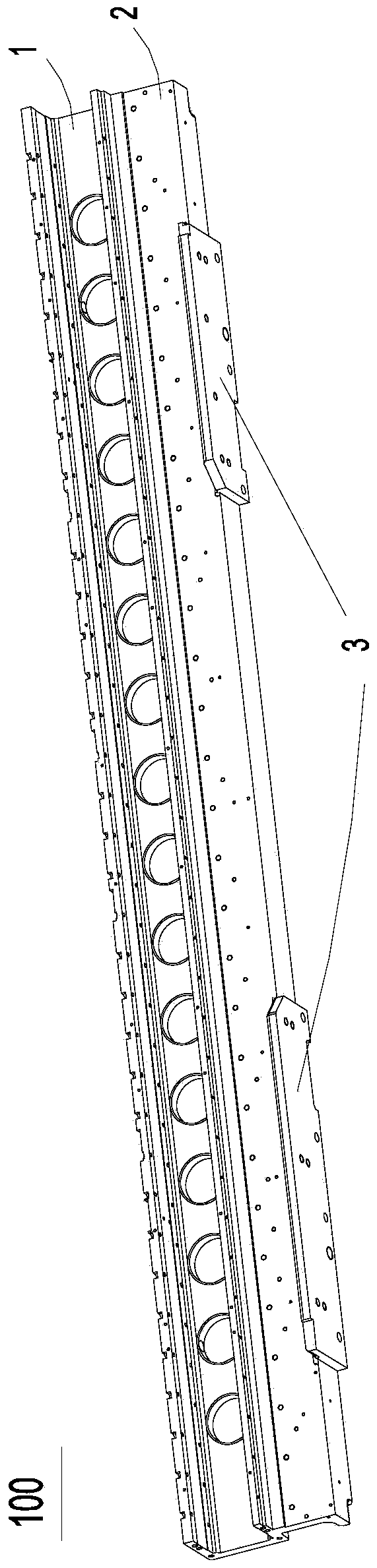
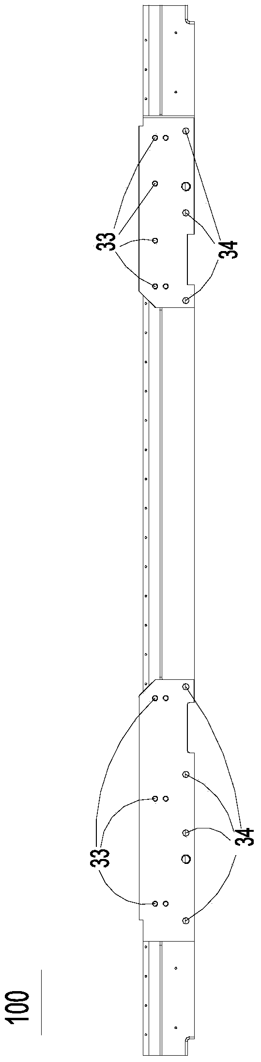
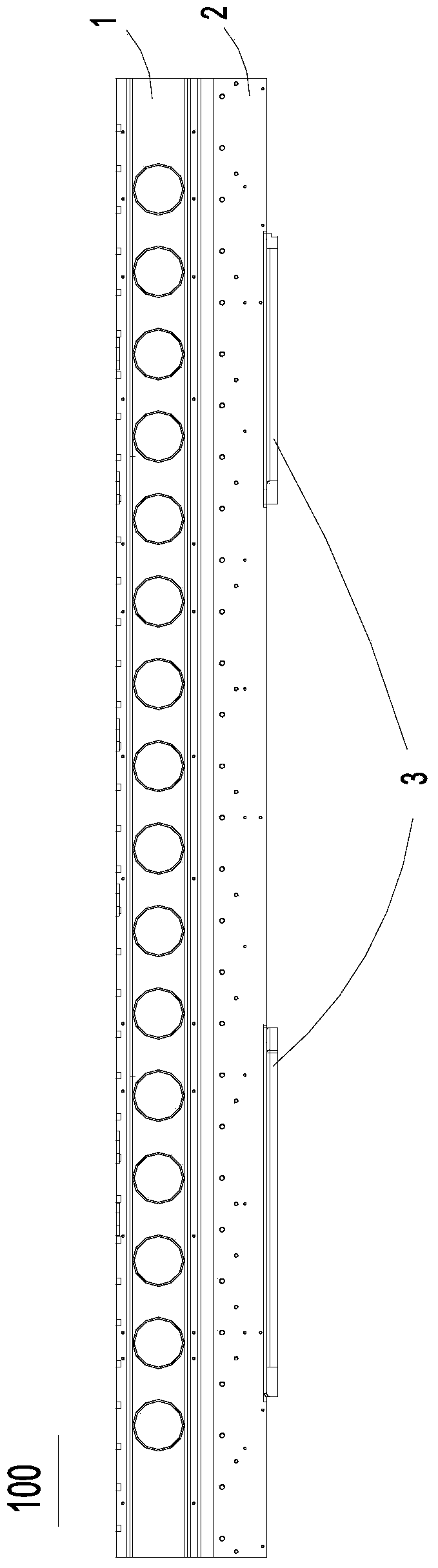
[0026] like Figure 1-4 As shown in the mounter guide rail seat, the mounter guide rail seat 100 includes a chute part 1, a vertical part 2 and a pair of connecting parts 3 distributed left and right from top to bottom. The chute part 1 has a chute 11 with the notch facing forward, the mouth of the chute 11 has a pair of notch surfaces 12 , and the inner surface of the chute 11 is an inner groove surface 13 . The vertical portion 2 is formed by extending downward from the lower middle area of ​​the chute 1 . A pair of connecting parts 3 are located at the bottom of the vertical part 2, and a pair of connecting parts 3 are respectively provided with a lower bottom surface 31, a front side 32 perpendicular to the lower bottom surface 31, a ...


PUM


Abstract

The invention discloses a method for machining a chip mounter guide rail seat through a gantry pentahedron numerical control machine tool. The method comprises the steps that the gantry pentahedron numerical control machine tool is firstly utilized for carrying out rough machining on a green body and machining the faces, corresponding to groove opening faces, of the green body to form a rough locating face; then, the green body is located and clamped with the rough locating face in the first procedure as the datum, side face semifinishing is carried out on the machine tool, and finish machining is carried out on the face corresponding to the rear side face to form a first locating face; the green body is located and clamped again with the first locating face as the standard, rough machining is carried out on the faces corresponding to the inner side groove faces of a sliding groove through the machine tool, and finish machining is carried out on the face corresponding to the lower bottom faces of connecting portions of the green body and the face corresponding to the front side faces of the connecting portions to form a second locating face and a standard face respectively; finally, the green body is located and clamped again with the second locating face as the fine datum face, and finish machining is carried out on holes and the faces corresponding to all the inner side groove faces of the sliding groove. The high-precision size can be machined successfully, and it is guaranteed that the machining quality of the chip mounter guide rail seat is stable 100 percent.

Description

technical field [0001] The invention relates to a method for processing slender and thin-walled workpieces, in particular to a method for processing a guide rail seat of a placement machine by using a Longmen pentahedron numerical control machine tool. Background technique [0002] The guide rail seat of the placement machine is the core component of the placement machine equipment. The length of the guide rail in this core component is about 3 meters, the wall thickness of the guide rail surface is only 16mm, and the parallelism and perpendicularity of some guide rail surfaces are required to be 0.01mm respectively. Each surface of the guide rail seat needs to be processed with multiple dimensions, and each clamping on this thin-walled guide rail will cause cumulative errors due to clamping stress and deformation. The clamping force is more likely to cause shape and size errors in finishing machining. [0003] Therefore, both chip deformation and clamping deformation of co...

Claims


Application Information

Patent Timeline
Patent Type & Authority Patents(China)
IPC IPC(8): B23P13/02B23Q17/22B23Q3/06
CPCB23P13/02B23Q3/064B23Q3/065
Inventor 刘军广吴炯陈京飙袁邦金
Owner SUZHOU IND PARK ELECTROMECHANICAL EQUIP
Why Eureka
Try Eureka